Introduction
5
1
1.5 Overview
This section identifies the components of the GV-IP Decoder Box.
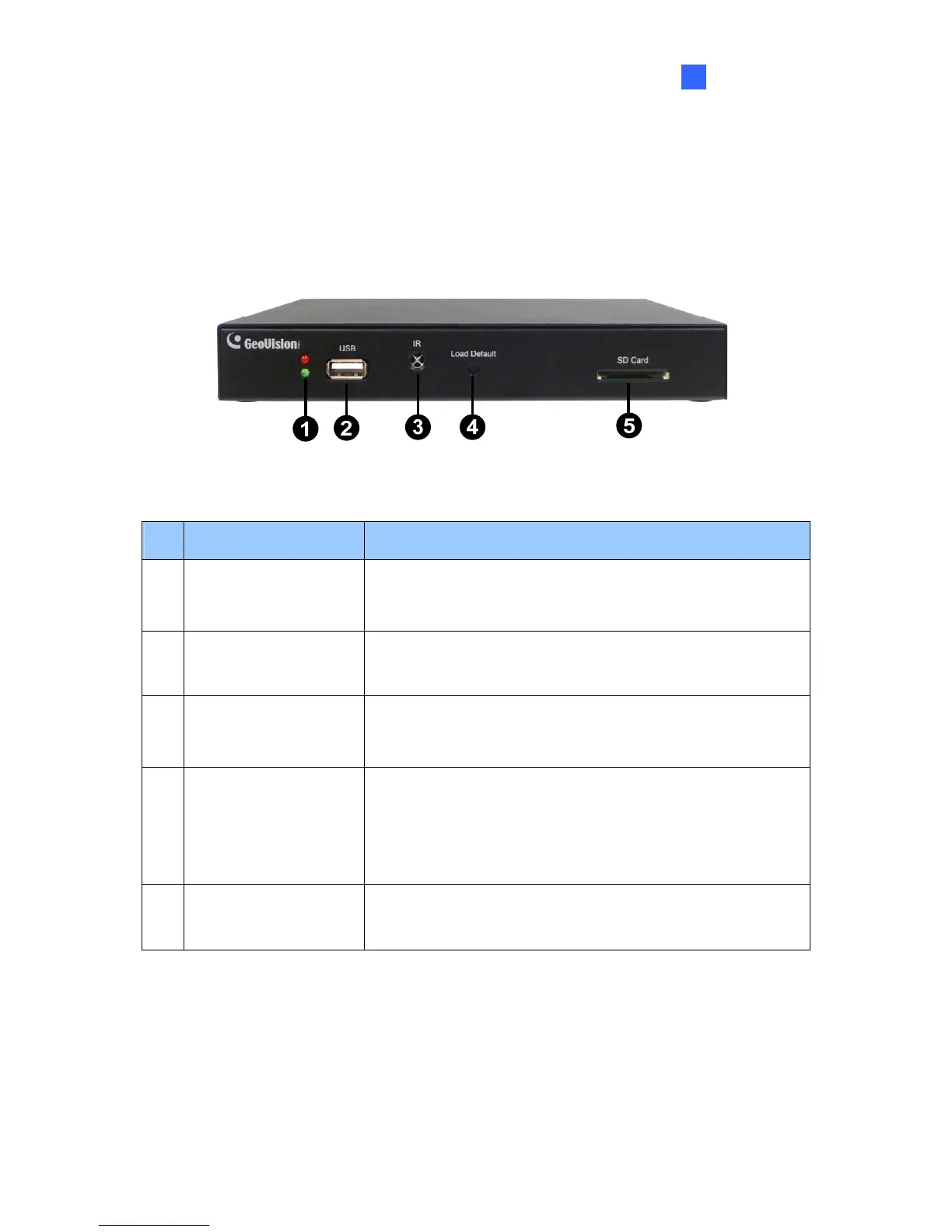
1.5.1 Front View
Figure 1-2
No. Name Function
1 LED Indicators
The green LED indicates the system is ready for use.
The red LED indicates the power is supplied.
2 USB
Connect to a GV-Joystick, or to a USB storage device for
local storage of snapshot and firmware upgrade.
3 IR
Built-in IR receiver to receive the IR signals from the IR
remote control.
4 Default
Reset the GV-IP Decoder Box to the default factory settings.
Use a pin to press the default button until the green LED
fades. This will take about 10 seconds. The system will then
reset and reboot itself shortly.
5 SD Card Slot
Connect to an SD card for local storage of snapshot and
firmware upgrade.