EasyManuals Logo

GeoVision GV-IP Decoder Box User Manual

GeoVision GV-IP Decoder Box
59 pages
To Next Page IconTo Next Page
To Previous Page IconTo Previous Page
Page #51 background imageLoading...
Page #51 background image
Introduction
45
4
4.5 Overview
This section identifies the components of the GV-Pad.
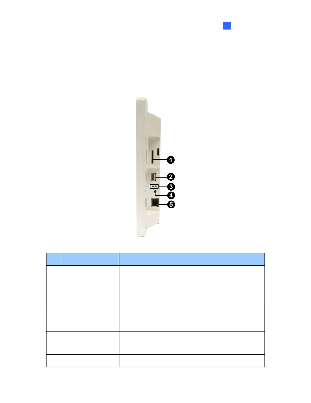
4.5.1 Right Panel View
Figure 4-2
No. Name Function
1 SD Card Slot
Connect to an SD card for local storage of snapshot and
firmware upgrade.
2 USB
Connect to a GV-Joystick, or to a USB storage device for
local storage of snapshot and firmware upgrade.
3 LED Indicators
The green LED indicates the system is ready for use.
The red LED indicates the power is supplied.
4 IR
Built-in IR receiver to receive the IR signals from the IR
remote control.
5 Network Connect to the network.

Other manuals for GeoVision GV-IP Decoder Box

Questions and Answers:

Question and Answer IconNeed help?

Do you have a question about the GeoVision GV-IP Decoder Box and is the answer not in the manual?

GeoVision GV-IP Decoder Box Specifications

General IconGeneral
BrandGeoVision
ModelGV-IP Decoder Box
CategoryNetwork Hardware
LanguageEnglish

Related product manuals