GV-Reader1251 / 1352 V2 and GV-SR1251
5
1
1.3 Connecting the Reader to GV-AS Controller
The GV-Reader1251 / 1352 V2 / SR1251 is compatible with any standard access controllers.
The following diagrams illustrate how to connect the GV-Reader1251 / 1352 V2 / SR1251 to
GV-AS Controller through Wiegand interface or RS-485 interface, and how to connect the
GV-Reader1251 / 1352 V2 / SR1251 to third-party access controllers and GV-DVR/NVR.
For GV-Reader1251 / 1352 V2, after you wire the connection between the reader and the
access controller, ensure the related switch setting on the GV-Reader1251 / 1352 V2 is
configured correctly.
Note: Each reader consumes 60 mA of power. The total power consumption of the output
devices and readers connected to GV-AS Controller must be under 2.5A (for GV-CS1320),
3A (for GV-AS1620, GV-AS210 / 2110 / 2120), 3.5A (for GV-AS410 / 4110) or 5A (for GV-
AS810 / 8110). Connect an external power supply if the power supplied from GV-AS
Controller is insufficient.
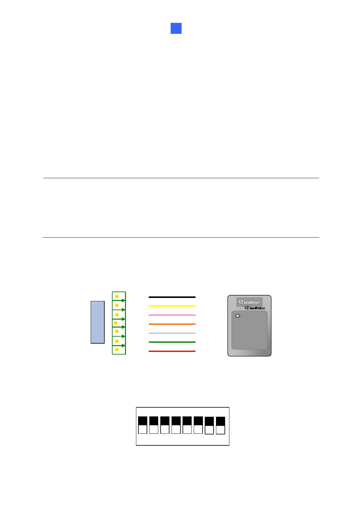
1.3.1 Connecting GV-AS Controller through Wiegand Interface
12V
D0
D1
GL
RL
BZ
Wiegand
GV-AS Controller
(Black)
(Yellow)
(Light red)
(White)
(Orange)
(Green)
(Red)
GV-Reader
GV-Reader
Switch Setting for Wiegand Connection (GV-Reader1251 / 1352 V2 only)
1 2 3 4 5 6
7 8
ON ECE
SW4 must be turned ON.
 Loading...