6
1.3.2 Connecting to GV-AS Controller through RS-485 Interface
12V
-
+
GND
(Black)
(Blue)
(Light blue)
(Red)
GV-AS Controller
GV-Reader
GV-Reader
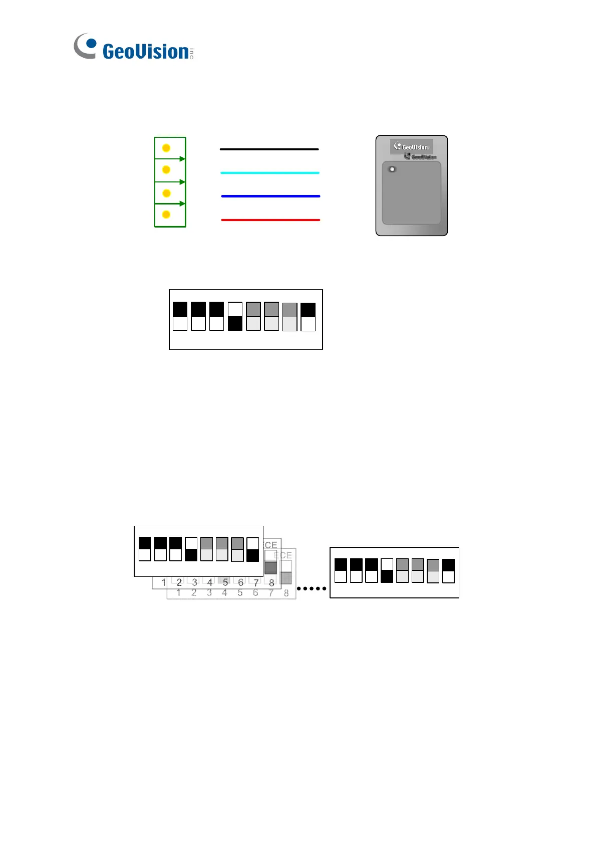
Switch Setting for RS-485 Connection (GV-Reader1251 / 1352 V2 only)
1 2 3 4 5 6
7 8
ON
ECE
SW4 must be turned OFF.
Switch Setting for Connecting Multiple GV-Readers (RS-485) (GV-Reader1251 / 1352
V2 only)
Multiple readers can be connected to GV-AS Controller through a single RS-485 cable.
When you connect more than one GV-Reader to GV-AS Controller, on the last
connected GV-Reader turn SW8 to ON. Make sure to define the ID of each reader with
SW5 to SW7 first.
GV-Reader 1 GV-Reader 8
1 2 3 4 5 6
7 8
ON
ECE
1 2 3 4 5 6
7 8
ON
ECE
ID Number Setting for Connecting Multiple GV-Readers (RS-485) (GV-SR1251 only)
Multiple readers can be connected to GV-AS Controller through a single RS-485 cable.
To define the ID of each GV-SR1251, see 1.2.3 Defining the ID Number of GV-SR1251
by Using GV-Reader Config Utility.

 Loading...