GV-RK1352 / R1352 / DFR1352
27
2
2.6.2 Wiring the Beeper and LED to GV-AS Controller
To wire the beeper and LED to GV-AS210 / 2110 / 2120 / 410 / 4110 / 810 / 8110, connect
the control wires of the reader’s Beeper, Red LED or Green LED to any of the outputs on
GV-AS Controller.
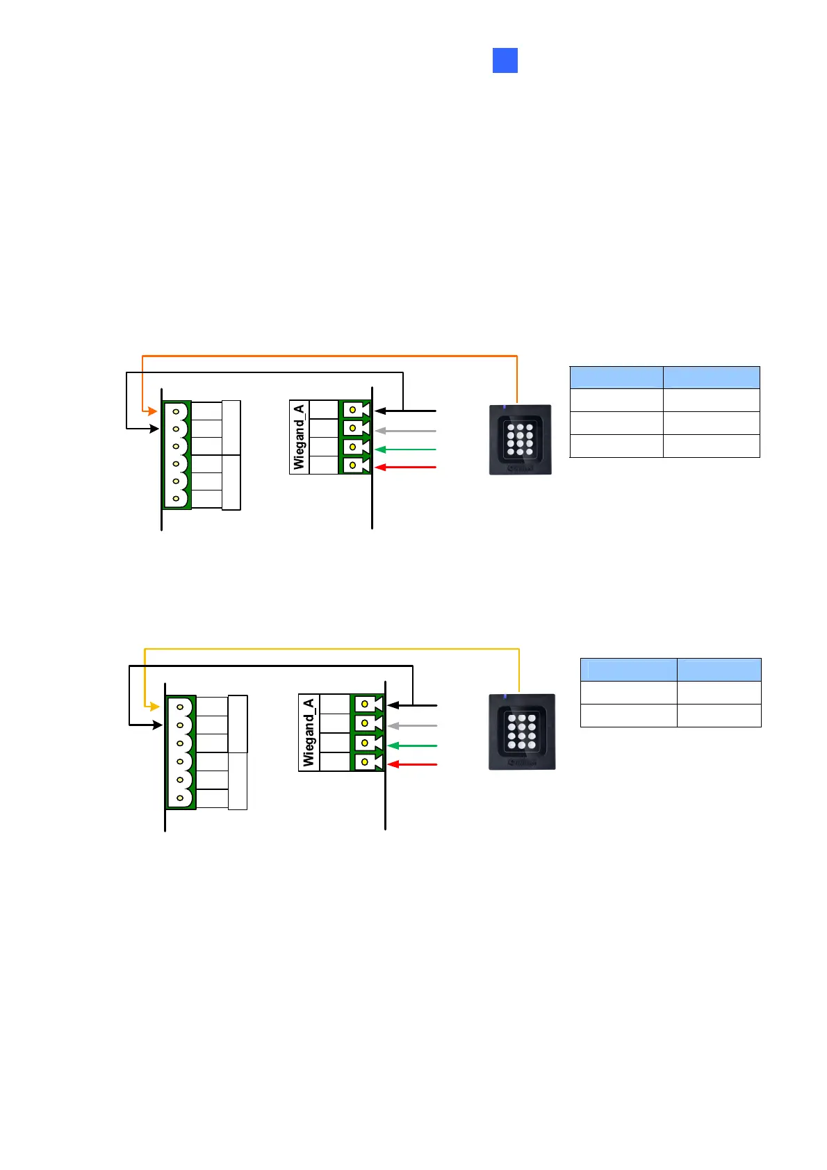
Wiring LED to GV-AS Controller
The diagram below shows the connection for wiring Green LED using GV-RK1352 and GV-
AS810 as an example. For Red LED, use the light red wire instead.
Wire Color Function
Black GND
Orange Green LED
Light Red Red LED
GV-AS810 Controller
GV-RK1352
or GV-R1352
OUT11
OUT12
NC
COM
NO
NC
COM
NO
Green LED (Orange)
12V
D0
D1
GND
(Black)
(Green)
(White)
(Red)
Wiring Beeper to GV-AS Controller
The diagram below shows the connection for wiring the beeper using GV-RK1352 and GV-
AS810 as an example.
Wire Color Function
Black GND
Yellow Beeper
GV-AS810 Controller
OUT11
OUT12
NC
COM
NO
NC
COM
NO
Beeper (Yellow)
12V
D0
D1
GND
(Black)
(Green)
(White)
(Red)
GV-RK1352
or GV-R1352
 Loading...