4
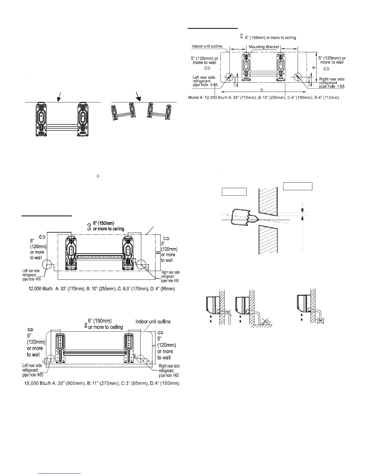
3. Install the mounting bracket on the wall with eight (8)
type “A” screws.
NOTE: Install the mounting bracket and drill the holes in the
wall according to the wall structure and the correspond-
ing mounting points on the mounting bracket. (The
mounting brackets vary according to the model.)
Incorrect orientation
of Installation Plate
Correct orientation
of Installation Plate
Figure 4
4. Determine the hole positions according to the diagram
detailed in Figures 5A & 5B (15 SEER) and 5C (19 SEER).
Drill one (1) 2.5” hole ( 65mm), slanting slightly to the
outside.
NOTE: Always use wall hole conduit when drilling metal
grid, metal plate, etc.
15 SEER MODELS
C
D
Indoor unit outline
Figure 5A - 12,000 Btu/h
C
D
Figure 5B - 18,000 Btu/h
19 SEER MODELS
Model B: 18,000 A: 31” (790mm), B:10” (265mm), C:4” (100mm), D: 6” (151mm)
Btu/h
C
D
Figure 5C - 12,000 Btu/h & 18,000 Btu/h
Refrigerant Piping & Condensate Piping
Installation:
5. Drain hose should be installed with a slight downward
slope. (See Figure 6.)
Wall
Indoor
Outdoor
5-7mm
3/16” -1/4”
Figure 6
Drain hose should NOT be installed as shown in Figure 7.
Do not block water flow by a rise.
Do not put the end of
drain hose into water.
Figure 7
6. When connecting extension drain hose, insulate the con-
necting part of the extension drain hose with a shield
pipe. Do not allow the drain hose to be slack.
 Loading...