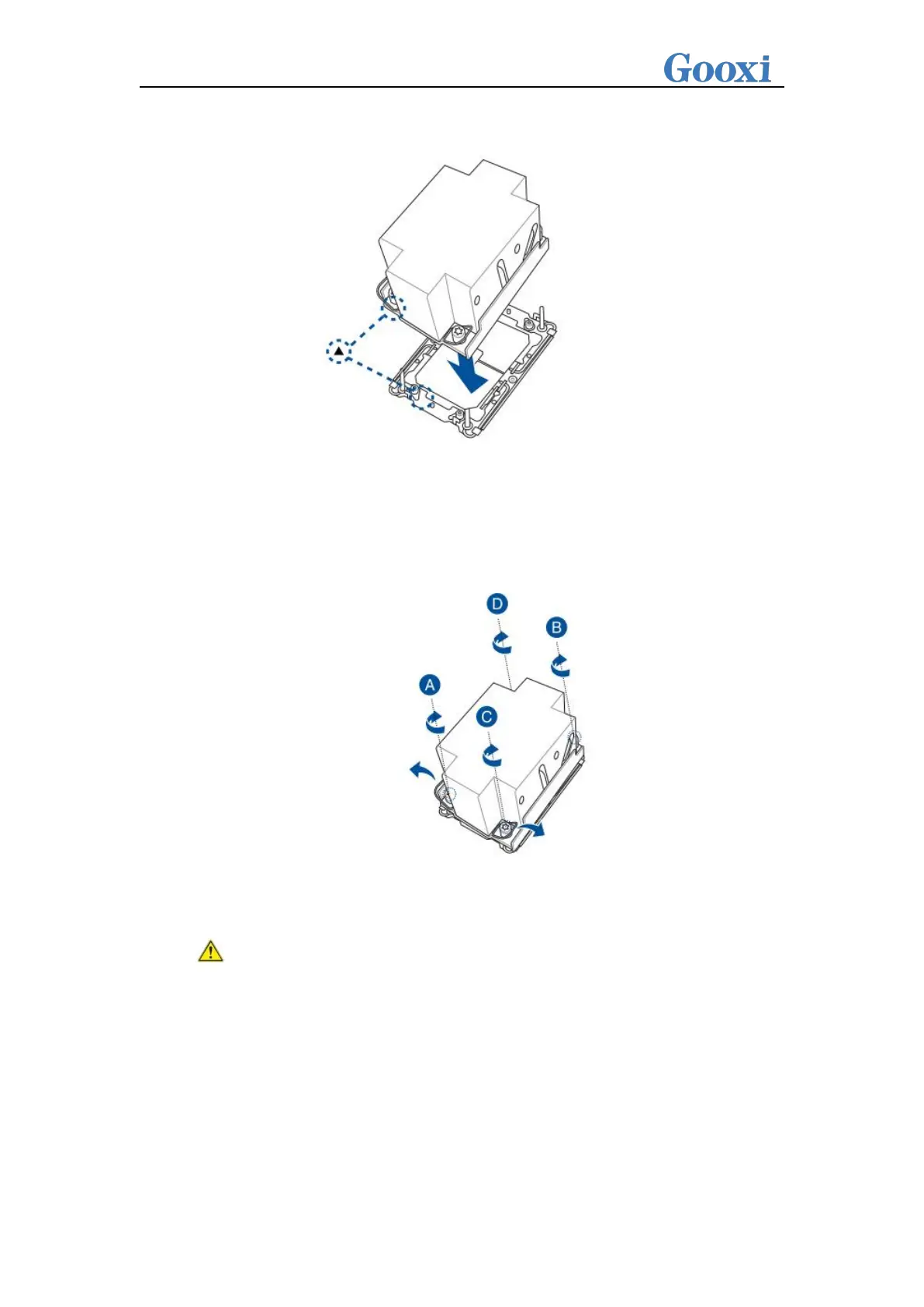
CPU socket. (As shown in the diagram below)
Figure 3-3
Step 4: Press down on the four corners of the heatsink's fixing lock towards
the outside, and, following the diagram below, rotate the screws fixing the
heatsink in a clockwise direction twice to secure the heatsink to the
motherboard.
Figure 3-4
Caution: The pins on the motherboard are extremely fragile and can be easily
damaged. To prevent damage to the motherboard, do not touch the processor
or the contact points on the processor socket.
3.2.2 Memory installation
The 16 memory slots controlled by CPU0 on the motherboard are as follows:
CPU0 DIMMB0/B1,DIMMA0/A1, DIMMD0/D1, DIMMC0/C1, DIMMG1/G0,
DIMMH1/H0, DIMME1/E0, DIMMF1/F0. The 16 memory slots controlled by CPU1
are as follows: CPU1 DIMMB0/B1,DIMMA0/A1,DIMMD0/D1,DIMMC0/C1,
DIMMG1/G0, DIMMH1/H0, DIMME1/E0, DIMMF1/F0. Please note that the memory
 Loading...