14 GMC-I Messtechnik GmbH
6.2 3-Phase Measurement (Line-to-Line Voltage) and Phase
Sequence
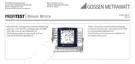
Connection
The measuring adapter
(2-pole) is required in
order to connect the
instrument, and is
expanded into a 3-pole
measuring adapter with
the included measure-
ment cable.
Ð Press softkey U3~
Clockwise phase sequence is generally required for all 3-phase elec-
trical outlets.
• Measurement instrument connection is usually problematic
with CEE outlets due to contact problems.
Measurements can be executed quickly and reliably without
contact problems with the help of the Z500A variable plug
adapter set available from GMC.
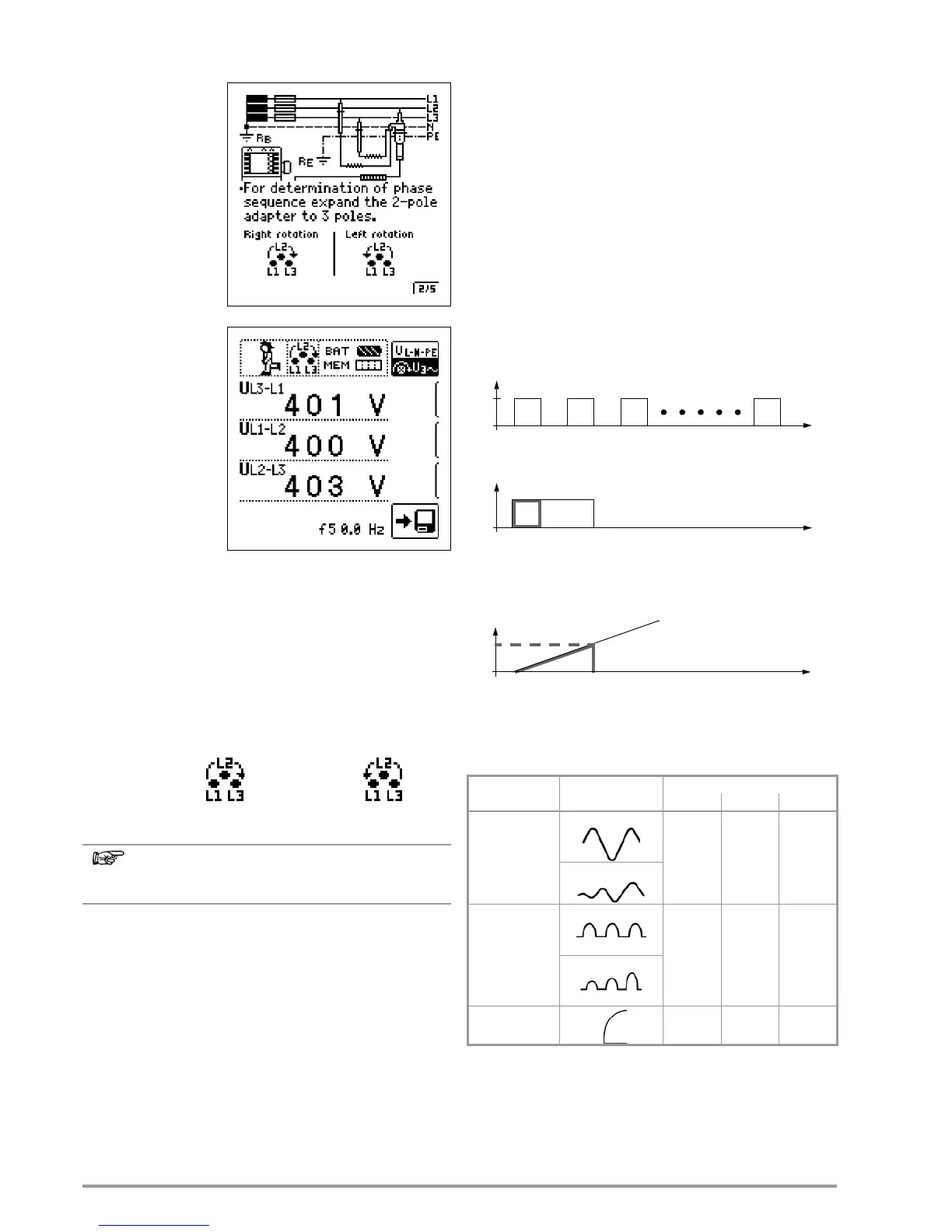
• Connection for 3-wire measurement, plug L1-L2-L3 in
clockwise direction as of PE socket
Direction of rotation is indicated by means of the following
displays:
See section 18.1 regarding all indications for the mains
connection test.
Voltage Polarity
If the installation of single-pole switches to the neutral conductor
is prohibited by the standards, voltage polarity must be tested in
order to assure that all existing single-pole switches are installed
to the phase conductors.
7 Testing RCDs
The testing of residual current devices (RCDs) includes:
• Visual inspection
•Testing
•Measurement
The test instrument is used for testing and measurement.
Measuring Method
The following must be substantiated by generating a fault current
downstream from the RCD:
• That the RCD is tripped no later than upon reaching its nominal
fault current value
• That the continuously allowable contact voltage value U
L
agreed upon for the respective system is not exceeded
This is achieved by means of:
• Contact voltage measurement:
16 measurements with full-waves and extrapolation of I
N
• Substantiation of tripping within 400 ms or 200 ms with I
N
•
Substantiation of tripping current with rising residual current,
value must be between 50 and 100% of
I
N
(usually approx.
70%)
• N o premature tripping with the test instrument, because testing
is begin at 30% residual current (if no biasing current occurs
within the system).

 Loading...