GMC-I Messtechnik GmbH 29
10.2 Measuring Without Probe
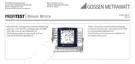
Earth Resistance Measurement without Probe (Mains Powered) – Connection Circuit Diagram
Key
R
B
Operational earth
R
E
Earth resistance
R
i
Internal resistance
R
X
Earth resistance via equipotential bonding systems
R
S
Probe resistance
PAS Equipotential bonding strip
RE Overall earth resistance (R
E1
//R
E2
//water pipe)
In the event that it is impossible to set a probe, earthing resis-
tance can be estimated by means of an “earth loop resistance
measurement” without probe.
The measurement is performed exactly as described in section
10.1, “Measuring with Probe”, beginning on page 28. However,
no probe is connected to the probe connector socket (17).
The resistance value R
ELoop
obtained with this measuring
method also includes operational earth electrode resistance R
B
and resistance at phase conductor L. These values must be
deducted from the measured value in order to determine earthing
resistance.
If conductors of equal cross section are assumed (phase conduc-
tor L and neutral conductor N), phase conductor resistance is half
as great as supply impedance Z
L-N
(phase conductor + neutral
conductor).
Supply impedance can be measured as described in section 9
beginning on page 25.
In accordance with DIN VDE 0100, the operational earth elec-
trode R
B
must lie within a range of “0 to 2 ”.
1) Measurement: Z
LN
corresponds to R
i
= 2 · R
L
2) Measurement: Z
L-PE
corresponds to R
Loop
3) Calculation:
R
E1
corresponds to Z
L-PE
– 1/2 · Z
L-N
; for R
B
= 0
The value for operational earth conductor resistance R
B
should be
ignored in the calculation of earthing resistance, because it is
generally unknown.
The calculated earthing resistance thus includes operational earth
conductor resistance as a safety factor.
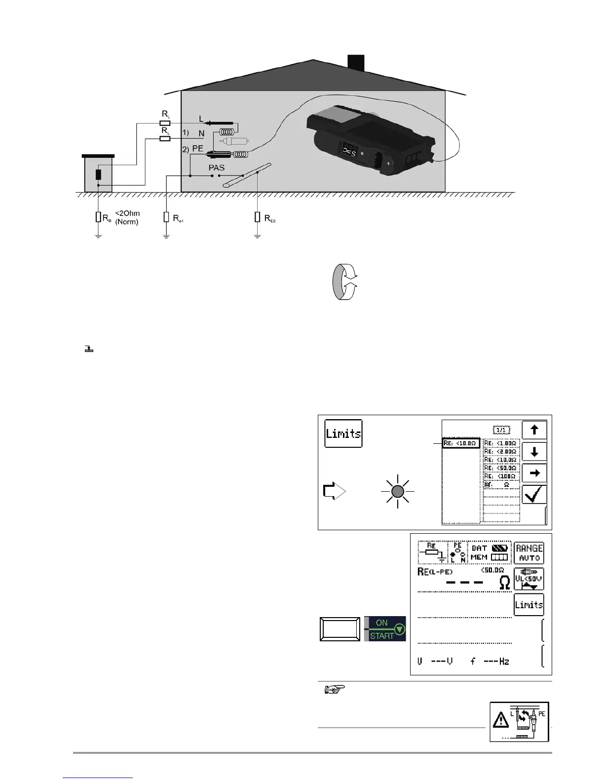
Select the Measuring Function
Set parameters
q Measuring range: AUTO,
10 k (4 mA), 1 k (40 mA), 100 (0,4 A), 10 (> 0.65 A)
In systems with RCCBs, resistance and/or test current must
be chosen such that they are below the tripping current
(˝½ I
N
).
q Connection type: 2-pole adapter
q Transformer ratio: without significance in this case
q Contact voltage: UL < 25 V, < 50 V, < 65 V
Start Measurement

 Loading...