Checking the Measurement Cables prior to a series of
measurements
Before performing insulation measurement, the test
probes on the measurement cables should be short-
circuited in order to assure that the instrument displays a
value of less than 1 k. In this way, incorrect connection
can be avoided and broken measurement cables can be
detected.
Set Parameters
* Freely adjustable voltage, see section 5.7
Semiautomatic Measurement in Multi-Pole Systems
* Refer to section 5.8 regarding AUTO parameter.
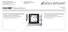
Limit Values for Constant Test Voltage
Limit Currents for Ramp Function
q Test Voltage
A test voltage which deviates from nominal voltage, and is usually
lower, can be selected for measurements at sensitive
components, as well as systems with voltage limiting devices.
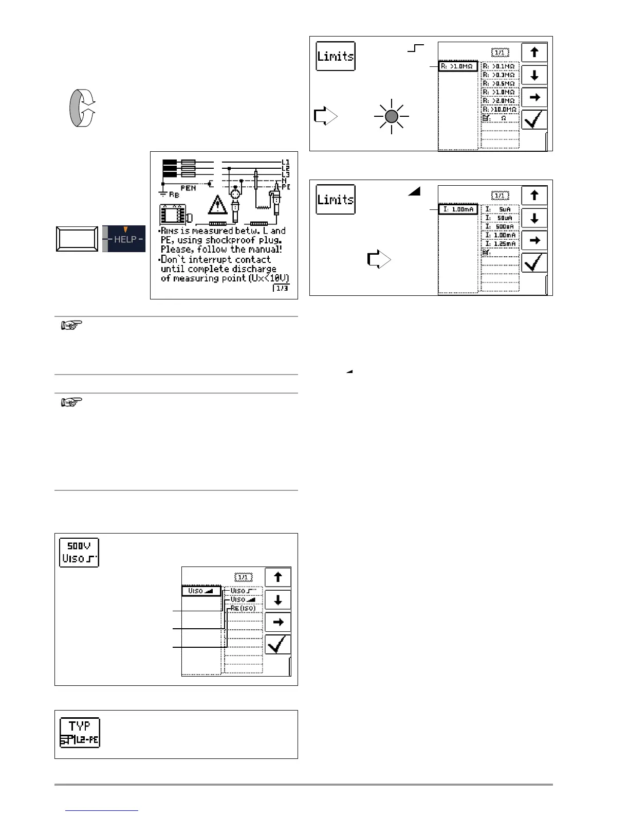
q Voltage Type
The “U
INS
” rising test voltage function (ramp function) is used to
detect weak points in the insulation, as well as to determine
response voltage for voltage limiting components. After briefly
pressing the ON/START key, test voltage is continuously increased
until specified nominal voltage U
N
is reached. U is the voltage which
is measured at the test probes during and after testing. This voltage
drops to a value of less than 10 V after measurement (see section
entitled “Discharging the Device Under Test”).
Insulation measurement with rising test voltage is ended:
• As soon as the specified maximum test voltage U
N
is reached
and the measured value is stable
or
• As soon as the specified test current is reached
(e.g. after spark-over occurs at breakdown voltage)
Selected maximum test voltage U
N
, or any available trigger or
breakdown voltage, is displayed for U
ISO
.
The constant test voltage function, or constant test voltage, offers
two options:
• As long as you press and hold the ON/START key, test voltage
U
N
is applied and insulation resistance R
INS
is measured.
Do not release the key until the measured value has stabilized
(in the case of high cable capacitance, it may take several
seconds to settle in).Voltage U, which is measured during
testing, corresponds to voltage U
INS
. After releasing the
ON/START key, measurement is ended and the last measured
values for R
INS
and U
INS
are displayed. U drops to a value of
less than 10 V after measurement (see section entitled
“Discharging the Device Under Test”).
or
• After briefly pressing the ON/START key, specified test voltage
U
N
is read out and insulation resistance R
INS
is measured. As
soon as the measured value is stable (in the case of high cable
capacitance, it may take several seconds to settle in),
measurement is ended and the last measured values for R
INS
and U
INS
are displayed. U is the voltage which is measured at
the test probes during and after testing. This voltage drops to a
value of less than 10 V after measurement (see section entitled
“Discharging the Device Under Test”).

 Loading...