Test Instrument and Adapter
1 Control panel with keys and
display panel with snap in
function for ideal viewing angle
2 Eyelets for attaching the
shoulder strap
3 Rotary selector switch
4 Measuring adapter (2-pole)
5 Plug insert (country specific)
6 Test plug (with retainer ring)
7 Alligator clip (plug-on)
8 Test probes
9 t key ON/START *
10 Key I I
N
/compens./Z
OFFSET
11 Contact surfaces for finger
contact
12 Test plug holder
13 Fuses
14 Holder for test probes (8)
Connectors for current clamp / probe
15 Current clamp connection 1
16 Current clamp connection 2
17 Probe connection
Interfaces, Charger Connection
18 USB slave for PC connection
19 RS 232 for connecting a
barcode scanner or an RFID
reader
20 Connection for Z502P charger
Attention!
Make sure that no batteries
are inserted before
connecting the charger.
21 Battery compartment lid
(compartment for rechargeable
batteries and replacement fuses)
Please refer to section 17 for
explanations regarding con-
trol and display elements.
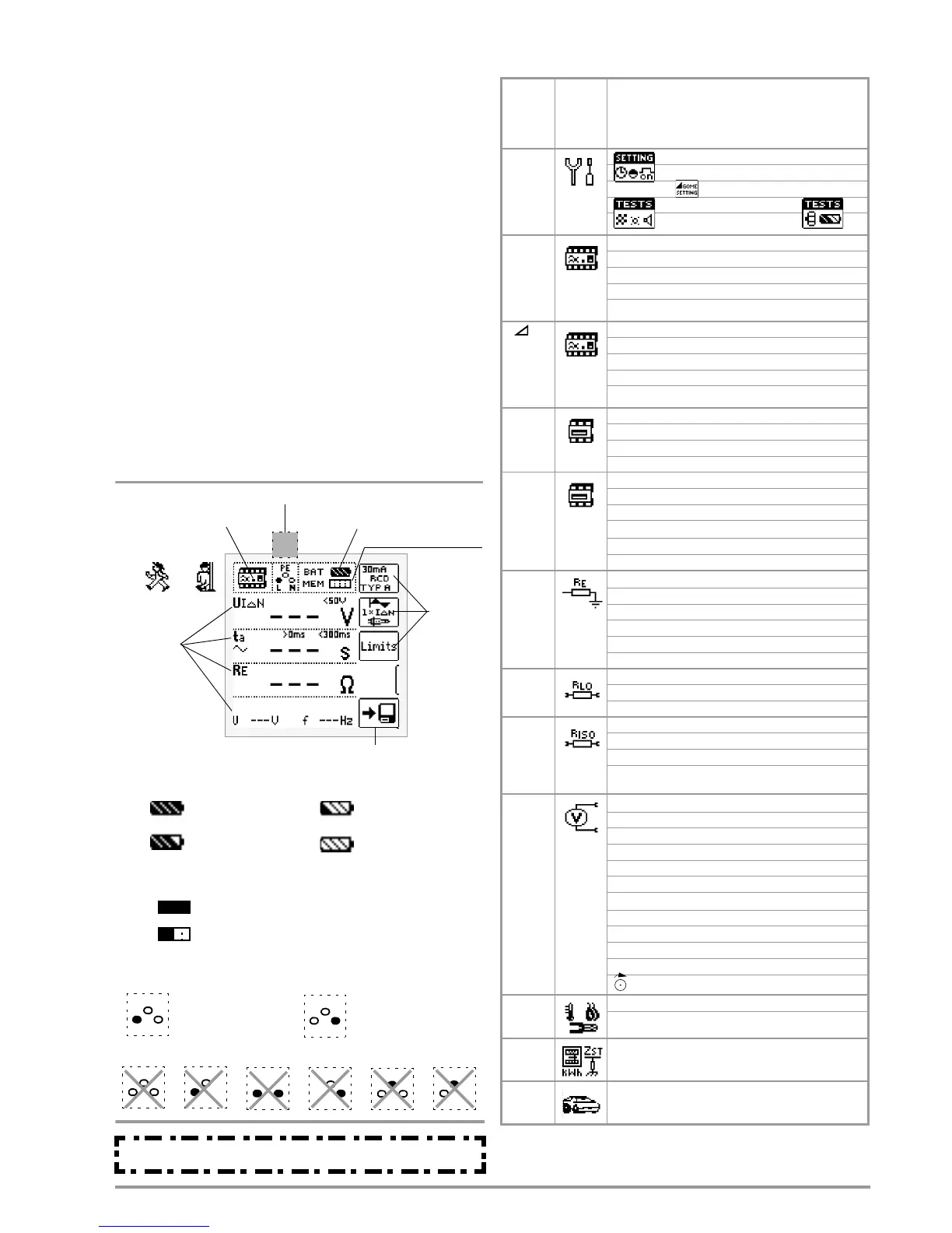
Battery Level IndicatorMeasuring Function
Measurement
Memory Occupancy
Measured
Parameters
Display Panel
PE
Manual: Save Value
Battery full
Battery OK
Battery weak
Battery (nearly)
Battery Level Indicator
BAT
BAT
BAT
BAT
Memory Occupancy Display
MEM
Memory half full
MEM
Memory full, transfer data to PC
Connection Test – Mains Connection Test ( section 18.1)
Connection OK L and N reversed
RUN READY
Connection test section 18.1
depleted: U < 8 V
Quantities
in progress/stopped
N
PE
L
N
PE
L
)(
N
PE
L N
PE
L
x
N
PE
L N
PE
L
x
x
L
PE
N
x
L
PE
N
* Power ON only possible via instrument key
Switch
position
descrip-
tion on
page ...
Picto-
graph
Device Settings
Measuring Functions
SETUP
Page 7
Brightness, contrast, Date/time
Language (D, GB, P), Profile (ETC, PC.doc)
Default settings
< Test: LED, LCD, Acoustic signal
Rotary switch balanc., batt. level >
IN
Page 15
UIN Contact voltage
ta Tripping time
RE Earth resistance
U / U
N
Line voltage / Nominal line voltage
f / f
N
Line frequency / Nominal line frequency
IF
Page 17
UIN Contact voltage
I Residual current
RE Earth resistance
U / U
N
Line voltage / Nominal line voltage
f / f
N
Line frequency / Nominal line frequency
ZL-PE
Page 23
ZL-PE Loop impedance
IK Short-circuit current
U / U
N
Line voltage / Nominal line voltage
f / f
N
Line frequency / Nominal line frequency
ZL-N
Page 25
ZL-N Line impedance
IK Short-circuit current
U Voltage drop as a percentage
Z
OFFSET
Offset for voltage drop
U / U
N
Line voltage / Nominal line voltage
f / f
N
Line frequency / Nominal line frequency
RE
Page 27
Measurement with or without probe
RE (L-PE) Earth loop (without probe/clamp)
RE Earth resistance (with probe/clamp)
UE Earth electrode voltage (only with probe)
U / U
N
Line voltage / Nominal line voltage
f / f
N
Line frequency / Nominal line frequency
RLO
Page 38
RLO Low-resistance with polarity reversal
RLO+, RLO–
Low-resistance single-pole
R
OFFSET Offset resistance
RISO
Page 34
RINS Insulation resistance
RE(INS) Earth leakage resistance
U Voltage at the test probes
UINS Test voltage
Ramp: triggering/breakdown voltage
U
Page 13
Single-phase measurement U
L-N-PE
UL-N
Voltage between L and N
UL-PE
Voltage between L and PE
UN-PE
Voltage between N and PE
US-PE Voltage between probe and PE
f Frequency
3-phase measurement U
3~
UL3-L1 Voltage between L3 and L1
UL1-L2 Voltage between L1 and L2
UL2-L3 Voltage between L2 and L3
f Frequency
Phase Sequence
SENSOR
Page 40
I
L/AMP
Residual or leakage current
T/RF Temperature/humidity (in preparation)
EXTRA
Page 33
PTEST Meter start-up test
ZST Standing surface insulation impedance
AUTO
Automatic test sequences
(in preparation)
These operating instructions describe a test instrument with
software version SW-VERSION (SW1) 02.12.00.

 Loading...