28 GMC-I Messtechnik GmbH
10.1 Measuring with Probe
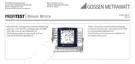
Earth Resistance Measurement with Probe (Mains Powered) – Connection Circuit Diagram
Key
R
B
Operational earth
R
E
Earth resistance
R
X
Earth resistance via equipotential bonding systems
R
S
Probe resistance
PAS Equipotential bonding strip
RE Overall earth resistance (R
E1
//R
E2
//water pipe)
Measurement R
E
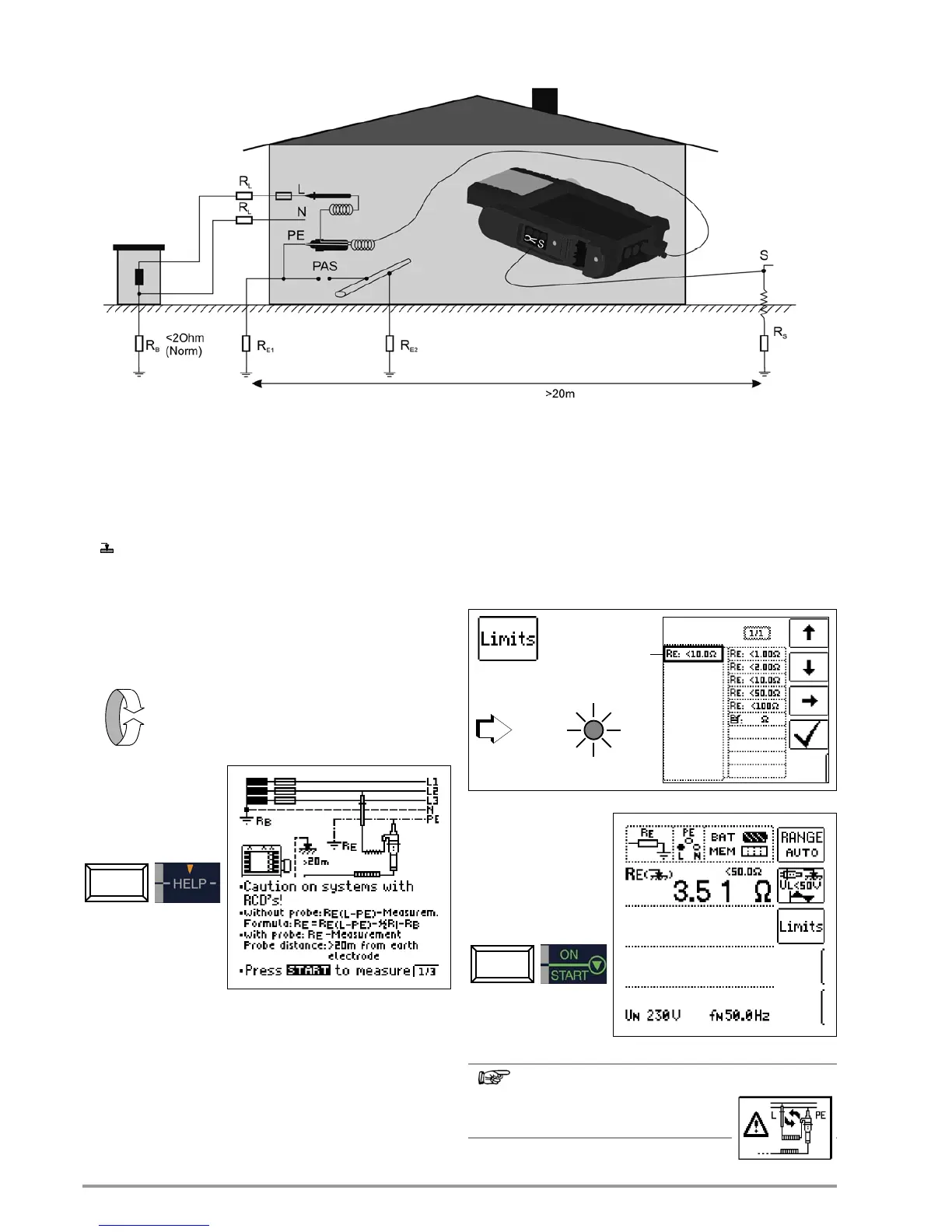
Select the Measuring Function
Connection
Connected components: 2-pole adapter and probe
Set parameters
q Measuring range: AUTO,
10 k (4 mA), 1 k (40 mA), 100 (0,4 A), 10 (> 0.65 A)
In systems with RCCBs, resistance and/or test current must
be chosen such that they are below the tripping current
(½ I
N
).
q Connection type: 2 pole adapter + probe
q Contact voltage: UL < 25 V, < 50 V, < 65 V, freely adjustable
voltage, see section 5.7
q Transformer ratio: without significance in this case
Start Measurement

 Loading...