GMC-I Messtechnik GmbH 31
10.4 Selective Earth Resistance Measurement with Accessory Current Clamp Sensor
As an alternative to the classical measuring method, it is possible to perform measurements with a current clamp sensor.
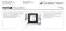
Selective Earth Resistance Measurement (Mains Powered) – Connection Circuit Diagram
Key figure below
R
B
Operational earth
R
E
Earth resistance
R
L
Conductor resistance
R
X
Earth resistance via equipotential bonding systems
R
S
Probe resistance
PAS Equipotential bonding strip
RE Overall earth resistance (R
E1
// R
E2
// water pipe)
Measurement without clamp: R
E
= R
E1
// R
E2
Measurement with clamp: R
E
= R
E2
=
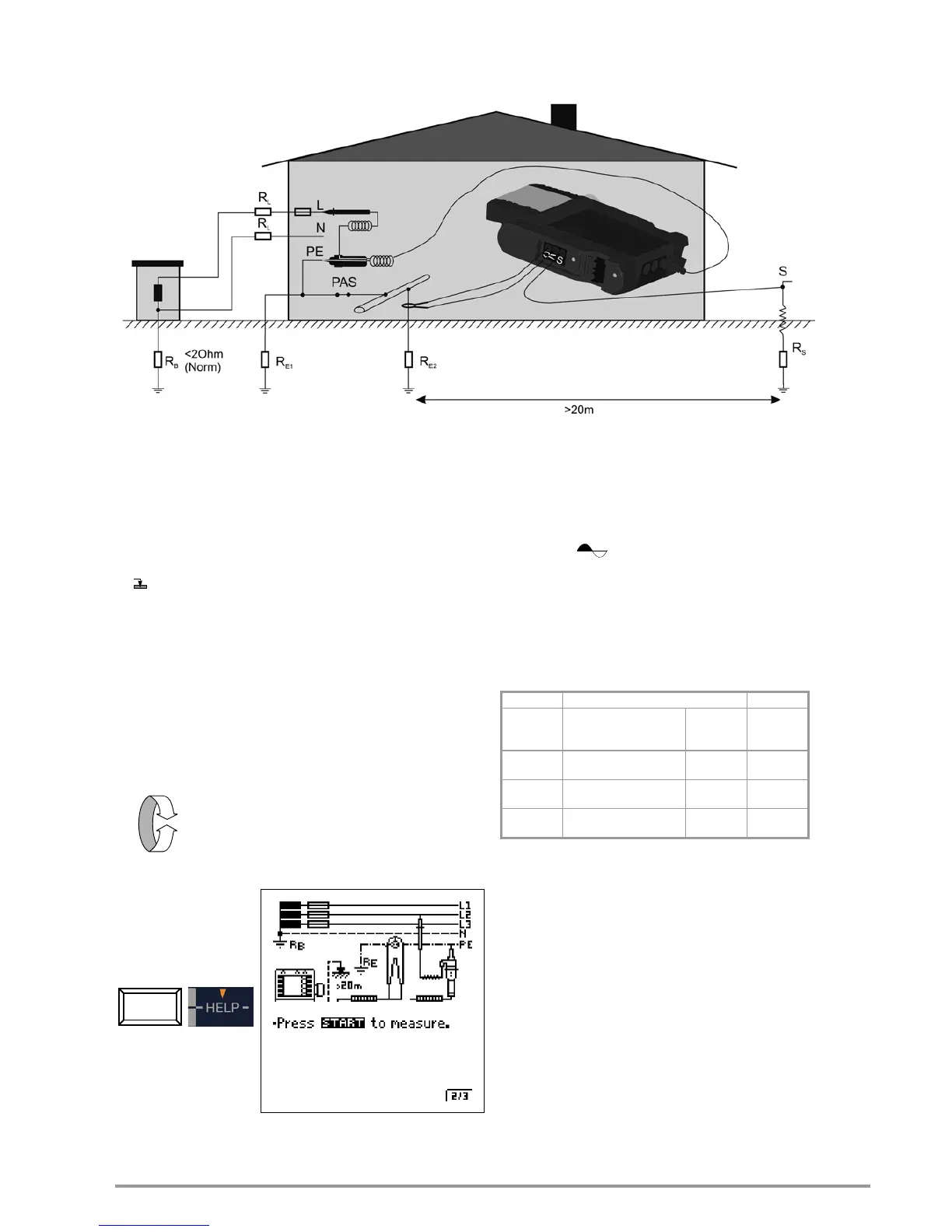
Select the Measuring Function
Connection
Connected components: 2-pole adapter, clamp sensor and probe
Set parameters at the test instrument
q Connection type: 2-pole adapter + clamp sensor
After parameter selection: automatic setting to 10
measuring range and transformer ratio of 100 mV/A
q Transformer ratio of current clamp sensor: see table below
q Measuring range (test current selection):
10 k (4 mA), 1 k (40 mA), 100 (0.4 A), 10 (> 0.65 A)
The DC + function can be selected for systems with
RCCB.
q Contact voltage: UL < 25 V, < 50 V, < 65 V, freely selectable
voltage, see section 5.7
Setting Parameters at the Current Clamp Sensor
q Measuring range of current clamp sensor: see table below
Select the Measuring Range at the Current Clamp Sensor
Important Instructions Regarding the Use of the Current Clamp Sensor
• Use only the METRAFLEX P300 or Z312A current clamp
sensor for this measurement.
• Read and adhere strictly to the operating instructions for the
METRAFLEX P300 current clamp sensor, as well as the safety
precautions contained therein.
• Be sure to observe the direction of current flow (see arrow on the
current clamp sensor).
• The clamp must be securely attached for use. The sensor must
not be permitted to move during measurement.
• The current clamp sensor may only be used at an adequate
distance from strong, extraneous fields.
• Before use, always inspect the electronics housing, the
connector cable and the flexible current sensor for damage.
• In order to prevent electrical shock, keep the surface of the
METRAFLEX clean and free of contamination.
• Before use, make sure that the flexible current sensor, the
connector cable and the electronics housing are dry.

 Loading...