18 307-378
Air
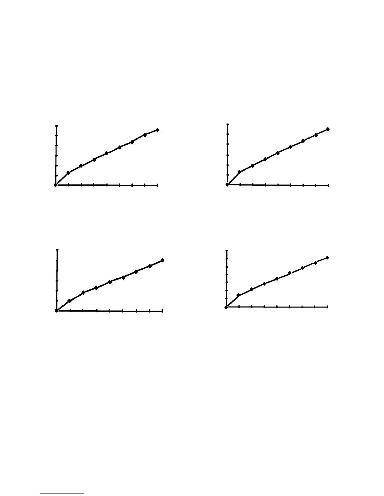
Flow Charts
Model 600–0–0
Part No. 217–600
12
4
0
0 10203040506070 80
Air Flow
(SCFM)
Air Pressure (psig)
Model 600–02–02
Part No. 217–601
Air Flow
(SCFM)
Air Pressure (psig)
0 1020304050607080
8
2
0
10
12
Model 600–2–2
Part No. 217–602
Air Flow
(SCFM)
Air Pressure (psig)
5
1
0
6
0 1020304050607080
(Gun Model – Nozzle – Air Cap)
10
8
6
6
4
4
3
2
Model 600–3–31
Part No. 217–605
Air Pressure (psig)
Air Flow
(SCFM)
6
4
0
8
12
0 1020304050607080
14
10
Each chart is headed by a gun model number
. The
first number refers to the 600 gun series. The next
number refers to the fluid nozzle. The last number re
-
fers to the air cap.
To use the charts:
1. Choose
the chart corresponding to your need.
2.
On the horizontal axis, note the air pressure that
will be used.
3.
Go up vertically until you intersect the actual air
flow line.
4.
Go across and read the air flow in scfm.
2
2