307-3785
Ordering
Charts
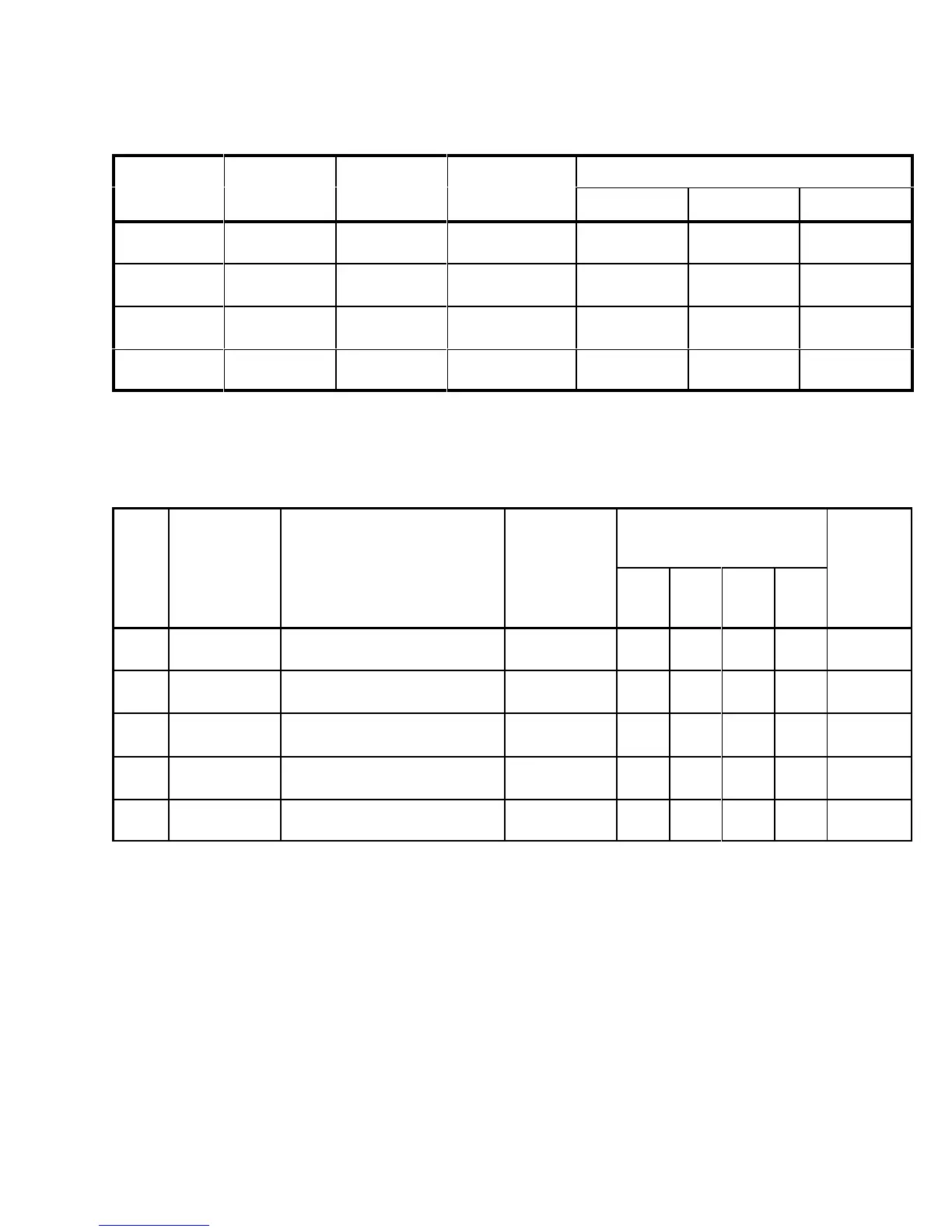
Chart 2: Fluid Nozzle/Needle Combinations*
Flow Rate
Recommended
Order
Part No.
Type
Orifice Size
fl. oz./min.
(liters/min.)
Usage
(See TERMS)
Kit Nozzle
Only
Needle Only
0
0.032”
(0.8
mm)
4–10
(0.12–0.30)
Light fluid
Pressure feed
106–639 106–610 106–622
02
0.039”
(1.0 mm)
8–17
(0.24–0.51)
Medium fluid
Pressure feed
106–640 106–611 106–623
2
0.051”
(1.3 mm)
4–8
(0.12–0.24)
Light fluid
Siphon feed
106–641 106–612 106–624
3
0.059”
(1.5 mm)
6–10
(0.18–0.30)
Medium fluid
Siphon feed
106–642 106–613 106–625
*
Needles and fluid nozzles are manufactured in matched, lapped sets and should be ordered as a kit to ensure
perfect seating of the needle in the fluid nozzle.
Chart 3: Air Caps Available
Pattern
Len
th
Air
Consump-
tion
Recommended Nozzle
Type
at 8 in.
(200 mm)
Pattern Shape
Recommended Usage
cfm at psi
(m
3
/min.
at bar)
0 02 2 3
Order
Part No.
0
4–8”
(100–200
mm)
Blunt
end pattern. Low production,
fine-finish
and touch-up.
8.5 at 50
(0.24 at 3.5)
X 106–600
02
6–10”
(150–250 mm)
Slight taper
. Low to medium pro
-
duction; general purpose.
8.1 at 50
(0.23 at 3.5)
X 106–601
2
3–6”
(75–150 mm)
Blunt end. Small work and
touch-up.
3 at 40
(0.08 at 2.8)
X 106–602
21
4–6”
(100–150 mm)
Medium taper
, low production,
metallics, touch-up and repair
.
7 at 40
(0.17 at 2.8)
X 106–603
31
5–7”
(125–175 mm)
Slight taper
. Medium production,
fine-finish, metallics, touch-up.
8 at 40
(0.22 at 2.8)
X 106–605
NOTE:
See page 18 for
Air Flow Charts
.