Wire Pattern Control Board
18 334784G
Wire Pattern Control Board
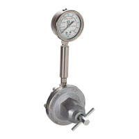
Valve Installation
1. Connect up to 8 valves.
NOTE: Control voltage is 24 VDC with a limit of 1
amp per output and 6 amps total.
NOTE: Green LEDs indicate the status of each
valve.
NOTE: DIN cable black wires are labeled 1 and 2. 1
is plus and 2 is minus.
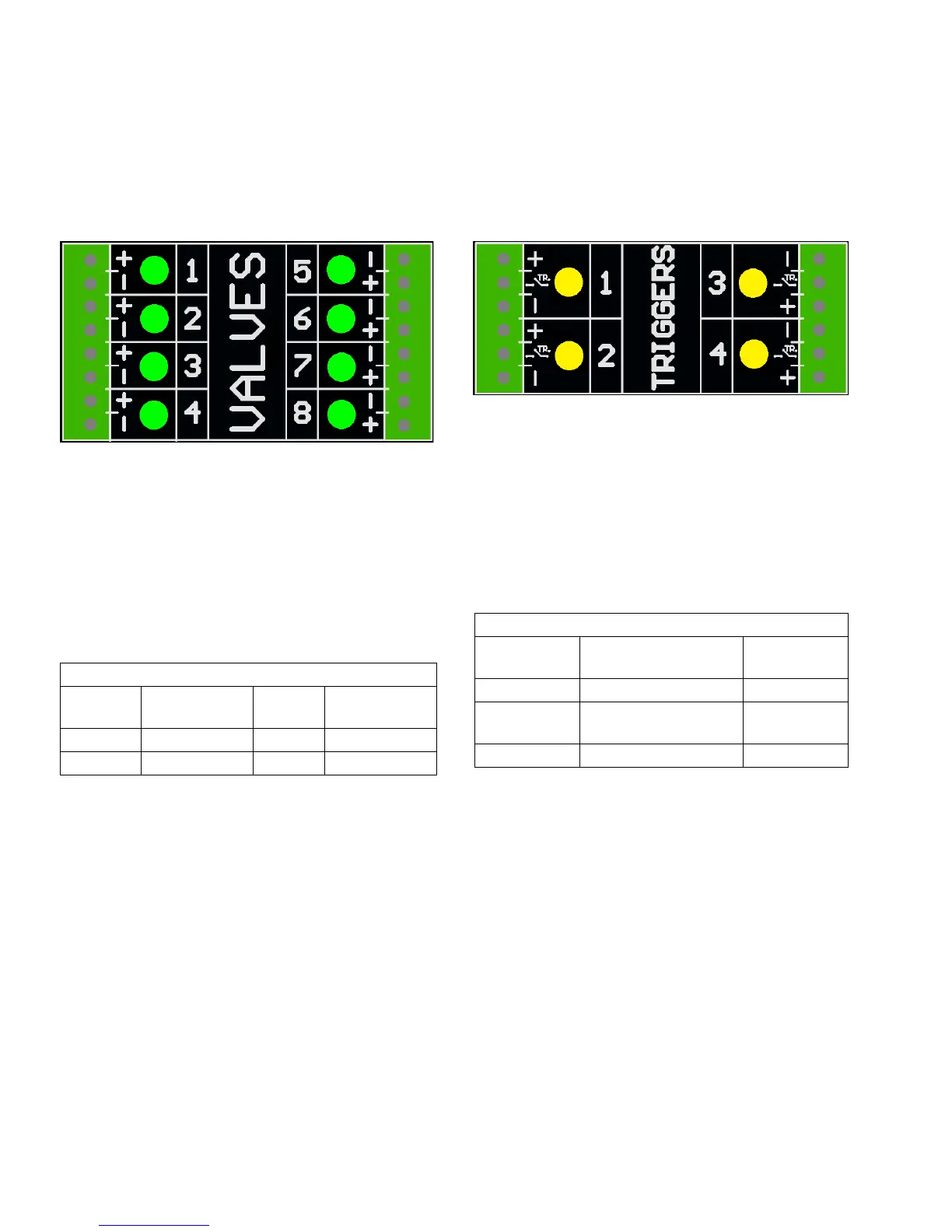
Trigger Installation
1. Connect up to 4 NPN, PNP, or dry contact triggers.
NOTE: Supplied voltage (+) is 24 VDC
2. Connect the two wires between TR and minus (-) to
install a dry contact.
NOTE: Yellow LEDs indicate the status of each trig-
ger. Polarity can be inverted if needed. See Trigger
Setup, page 31.
Standard Wiring Colors
Terminal
Cable
Function M8
Cable
DIN Cable
Plus (+) 24V Supply Brown Black 1
Minus (-) Return Blue Black 2
Standard Wiring Colors
Terminal Function M8 or M12
Cable
Plus (+) 24V Supply Brown
TR NPN, PNP, or dry con-
tact
Black or white
Minus (-) Return (or dry contact) Blue
 Loading...