Setup
312065V 21
Connect electrical cord
Do not install shutoffs downstream of the
PRESSURE RELIEF/SPRAY valve outlets (BA, BB).
The valves function as overpressure relief valves
when set to SPRAY . Lines must be open
so valves can automatically relieve pressure when
machine is operating.
If circulating fluid back to the supply drums, use high
pressure hose rated to withstand the maximum
working pressure of this equipment.
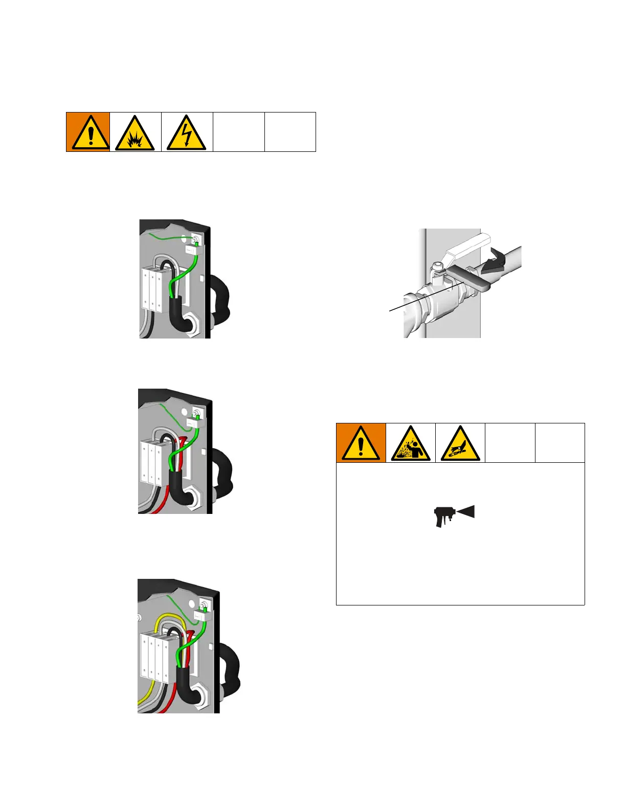
NOTE: Power cord is not supplied.
1. 200-240 V ac, 1-phase: Using 5/32 or 4 mm hex
allen wrench, connect two power leads to L1 and
L2. Connect green to ground (GND).
2. 200-240 V ac, 3-phase: Using 5/32 or 4 mm hex
allen wrench, connect three power leads to L1, L2,
and L3. Connect green to ground (GND).
3. 350-415 V ac, 3-phase: Using 5/32 or 4 mm hex
allen wrench, connect three power leads to L1, L2,
and L3. Connect neutral to N. Connect green to
ground (GND).
Connect feed pumps
1. Install feed pumps (K) in component A and B supply
drums. See FIG. 1 and FIG. 2, pages 12 and 13.
2. Seal component A drum and use desiccant dryer
(M) in vent.
3. Install agitator (L) in component B drum, if
necessary.
4. Ensure A and B inlet valves (FV) are closed.
NOTE: Supply hoses from feed pumps should be 3/4 in.
(19 mm) ID.
Connect pressure relief lines
1. Recommended: Connect high pressure hose (R) to
relief fittings (BA, BB) of both PRESSURE
L1
L2
GND
ti2515b
L1
L2
GND
ti3248b
L3
L1
L2
GND
ti2725a
L3
N
FV
TI10971a

 Loading...


