Operation
30 312065V
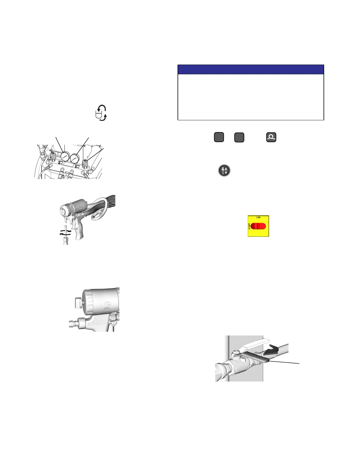
7. Check fluid pressure display and adjust as
necessary, see Set pressure, page 28.
8. Check fluid pressure gauges (GA, GB) to ensure
proper pressure balance. If imbalanced, reduce
pressure of higher component by slightly turning
PRESSURE RELIEF/SPRAY valve for that
component toward PRESSURE
RELIEF/CIRCULATION , until gauges show
balanced pressures.
9. Open gun fluid manifold valves A and B.
NOTE: On impingement guns, never open fluid
manifold valves or trigger gun if pressures are
imbalanced.
10. Disengage gun piston safety lock.
11. Test spray onto cardboard. Adjust pressure and
temperature to get desired results.
12. Equipment is ready to spray.
Shutdown
NOTICE
1. Shut off , , and heat zones.
2. Park pumps.
a. Press .
b. Trigger gun until pump A stops in the retracted
position and the pressure of both pumps bleeds
down.
3. Turn main power OFF .
4. Follow the Pressure Relief Procedure, page 25.
5. Turn off the air compressor and air dryer, if
included.
6. Open air compressor bleed valve to relieve
pressure and remove water from tank.
7. Turn off the main breaker on the generator.
8. Allow generator dwell time, per manufacturer
recommendations, prior to shutdown.
9. Close both fluid supply valves (FV).
10. Shut down feed pumps as required.
WLD
In this example, B side
pressure is higher, so
use the B side valve to
balance pressures.
GA
GB
ti2414a
ti2410a
Proper system setup, startup, and shutdown
procedures are critical to electrical equipment
reliability. The following procedures ensure steady
voltage. Failure to follow these procedures will cause
voltage fluctuations that can damage electrical
equipment and void the warranty.
A
B
ti10971a
FV

 Loading...


