23
A
B
C
E
F
D
Right
Side
12067
MOWING
Walk area before mowing, picking
up all rocks, twigs and other debris.
Enter new areas carefully. Cut grass
higher the fi rst time to allow mower to
clear unseen objects. Never assume an
area is clear - always check!
Clear mowing area of all people when
operating mower. Thrown objects
could injure bystanders.
Before starting to mow, position the ma-
chine in the area to be mowed with the
mower deck set at the desired cutting
height. With the engine at half throttle,
pull up on the PTO switch knob to start
the blades turning. Accelerate to full
throttle to begin mowing.
To avoid serious injury or death from
thrown objects or contact with blades,
NEVER operate mower without dis-
charge shield or restriction plate
installed.
Keep hands and feet away from dis-
charge opening.
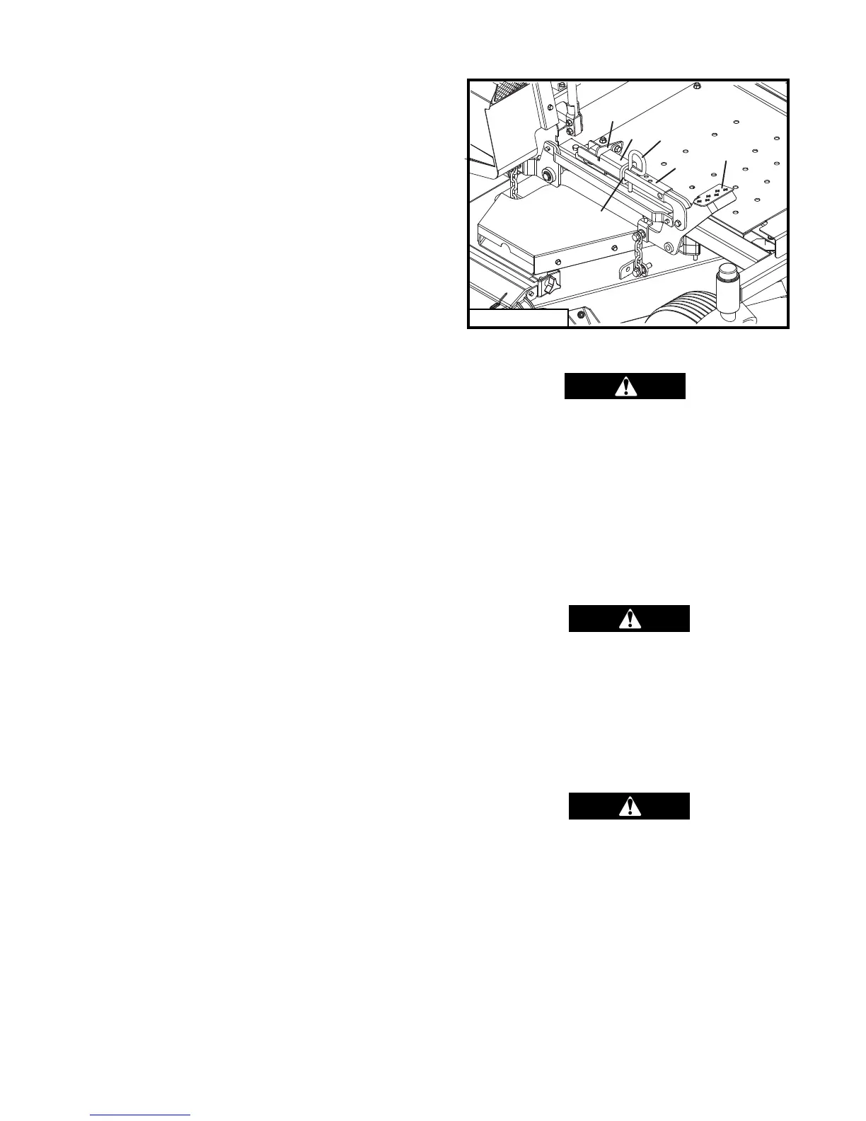
CUTTING HEIGHT ADJUSTMENT
(Refer to Fig. 5)
1. The mower deck cutting height adjustment
mechanism is located to the right front of
the operator seat on the deck carrier frame.
2. When adjusting cutting height always come
to a complete stop, disengage (down) the
PTO and wait for blades to stop rotating.
3. Pushing down on the foot lever (A) with
your foot will raise the deck and take pres-
sure off the height adjustment pin (B).
4. To change cutting height, push down on the
foot lever (A) and rotate the deck latch (F)
behind the latch tube guide (E) to support
the deck. This puts the deck in the transport
(5 inch cut) height position.
5. With the deck supported by the deck latch
(F), place the height adjustment pin (B) in
the hole indicated by the cutting height de-
cal for the desired cutting height.
6. To set the deck at this cut height, push down
on the foot lever (A) until pressure on the
deck latch (F) is released and lift the deck
latch (F) out from behind the latch tube
guide (E). Then slowly decrease pressure
on the foot lever (A) to allow the deck to
lower and the adjustment tube (C) to move
backward through the latch tube guide (E)
until the height adjustment pin (B) contacts
the end of the latch tube guide (E) and sup-
ports the deck.
7. Holes provided in the adjustment tube (C)
allow for cutting height adjustment in 1/2
inch increments. A height adjustment spac-
er (D) is provided to allow for cutting height
adjustment in .25 inch increments.
8. To set cutting height at a .25 inch increment,
the height adjustment spacer (D) should be
located between the height adjustment pin
(B) and the end of the latch tube guide (E).
9. To set the cutting height at a .5 inch in-
crement, the height adjustment spacer (D)
should be located forward of the height ad-
justment pin (B).
Fig. 5