33
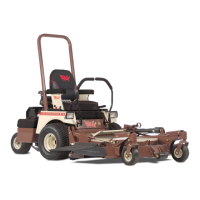
Fig. 12
with both levers full forward. If travel is
not in a straight line, adjust the steering le-
ver stop on the side that is the fastest, i.e.,
if machine goes to the left, adjust the right
steering stop to slow down the right trans-
mission until travel is straight ahead.
A
B
C
D
(Left Side Shown)
12077
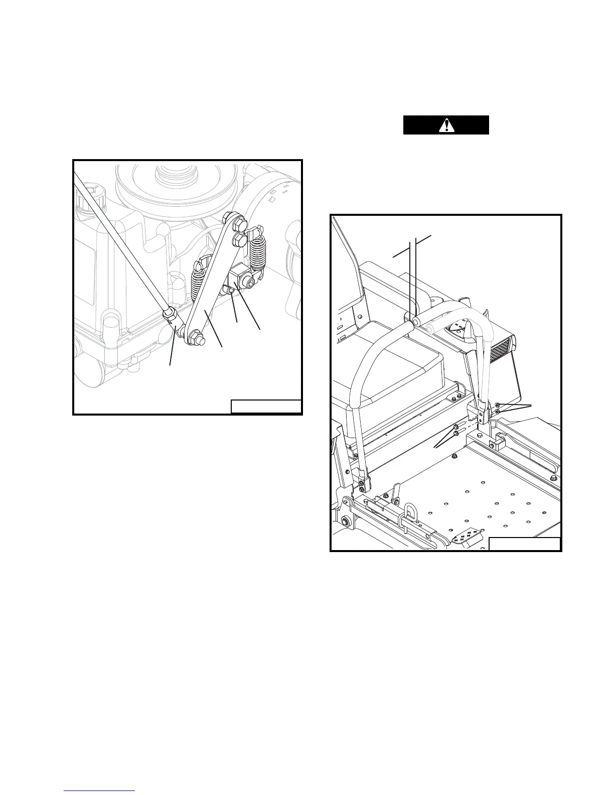
STEERING LEVER ADJUSTMENT
(Refer to Fig. 13)
Steering levers are secured to the lever mount
blocks with mounting bolts and nuts. A .5 inch
wrench is required to adjust the levers.
To adjust steering lever position, loosen nut on
the top mounting bolt. In the swung in (neutral)
position, the lever can now move forwards and
backwards without moving the lever mount. If
the lever mount moves with the steering lever,
the bottom mounting bolt may need to be loos-
ened. Set both levers in line and in a comfortable
position for the operator. Move levers to the
swung out (neutral lock) position and tighten top
nuts and bottom nuts if loosened. Both mount-
ing bolts MUST be tight to assure steering lever
control of the machine.
Steering levers must line up in the swung in
(neutral) position. Maintain one inch (25mm)
minimum clearance between ends of levers. If
1" minimum
Nuts
Bolts
12079
Fig. 13
the levers are allowed to lean toward the center
when the mounting bolts are tightened, free play
in the mounting holes may allow the levers to
hit each other.
When completing a maintenance
function, make sure all shields are in
good condition and are installed be-
fore placing unit back into use.