32
ADJUSTMENTS AND TROUBLESHOOTING
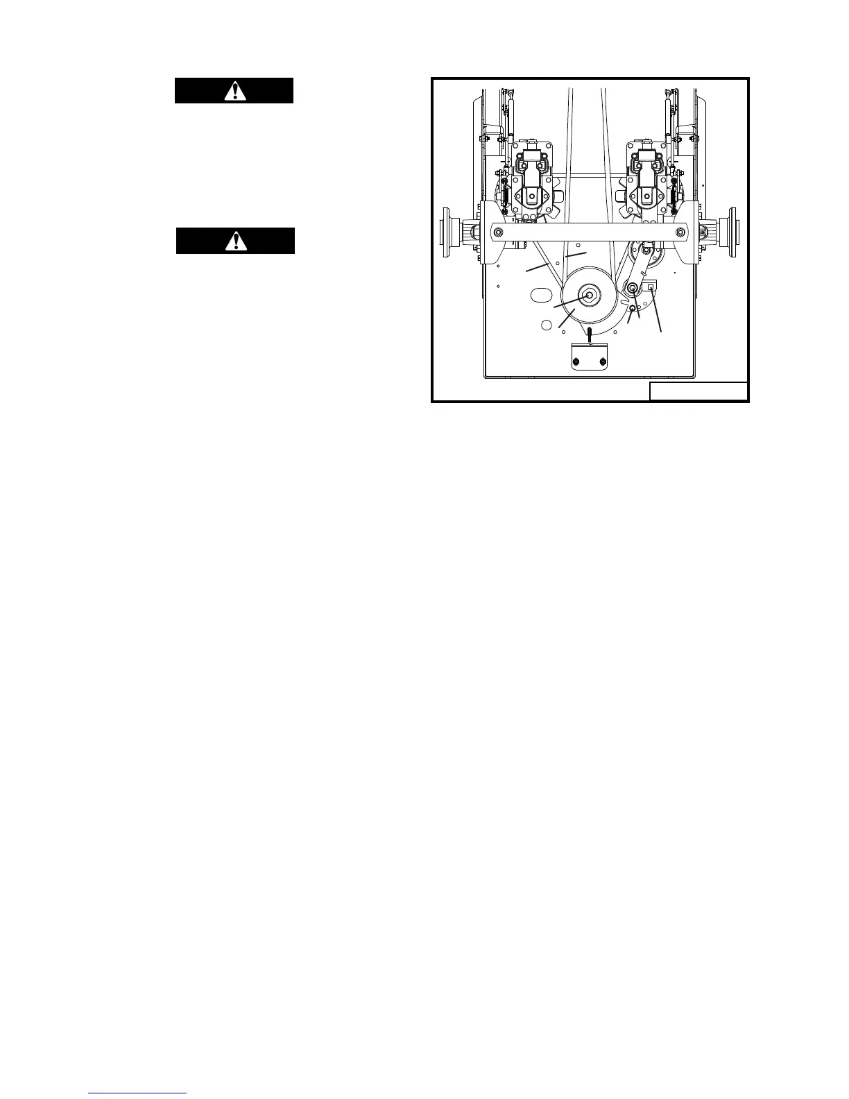
Fig. 11
Always make adjustments with the
machined parked on a hard level sur-
face; with the engine stopped and the
PTO disengaged; with the park brake
set; and with the key removed from
the ignition.
Always remove the grounded (-) clamp
from the battery when performing
maintenance on the engine, clutch, or
any other electrical system. Battery is
located under the right fender.
LOSS OF POWER IN THE DRIVE
SYSTEM
Check the fl uid level and make sure the proper
amount of fl uid is in the reservoir. Make sure all
hydraulic connections are tight and not leaking.
Make sure drive belt is tight and not slipping.
Check park brake adjustment. Make sure pump
bypass valve is tight so pump does not free-
wheel.
DRIVE BELT REPLACEMENT
(Refer to Fig. 11)
1. Remove the deck belt (A) as described in
“Deck Belt Replacement” section (page 37).
2. Remove the clutch center bolt (B) and slide
the clutch (C) off the engine's crankshaft.
3. Loosen the .375" idler arm pivot bolt (D)
and remove the .312" bolt (E) securing belt
tensioner bracket in place. Using a half
inch drive break-over bar or racket, inserted
in half inch square hole, rotate idler pulley
away from belt, relieving belt tension.
4. Remove the belt (F) from pulleys.
5. Install the new belt with the idler tension
bracket loose. Using the break-over bar,
reinstall the .312" bolt (E) (normally in
center hole) in the idler tensioner bracket
and secure. Do not over tighten belt. Belt
should only be tight enough to prevent belt
from slipping. Retighten .375 idler arm
pivot bolt (D).
6. Install the deck belt as described in “Deck
Belt Replacement” section (page 37).
NO POSITIVE NEUTRAL POSITION
If drive wheels travel forward or backward when
the steering lever is in swing-out position (neu-
tral), adjustment is required.
NEUTRAL ADJUSTMENT
(Refer to Fig 12)
1. Block up under tractor frame so both drive
wheels are off the ground.
2. Make sure parking brake is released.
3. Remove linkage rods (A) from transmission
neutral return arm (B).
4. Place steering levers in the neutral swing-out
position and start engine.
5. If either of the drive wheels turn, proceed
with the following adjustment.
6. With a .25" allen wrench loosen the socket
head cap screw (C) directly below the control
lever (D). Rotate the neutral return assem-
bly left or right until neutral is achieved.
Tighten socket head cap screw.
7. Repeat procedure for transmission on the
other side.
8. Reinstall linkage rod (A) in neutral return
arm (B). If ball joint does not reinstall into
neutral return arm without moving the return
arm, adjust length of linkage rod until it does
to assure neutral adjustment will be main-
tained when linkage is connected.
9. Test-drive machine for straight-line travel
A
B
C
D
E
1/2" SQ.
HOLE
F
12071