13
OPERATION
The safe operation of this machine is the respon-
sibility of the operator. Any person who operates
the machine MUST be instructed in and capable of
the safe operation of the machine and all controls.
Read all safety information on pages 6 through 10.
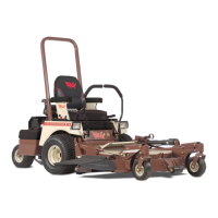
CONTROLS AND SWITCHES
(Refer to Fig. 3)
Know your controls and how to stop the ma-
chine, engine, and mower deck quickly in an
emergency. Do not operate this machine until
you are completely familiar with the controls
and comfortable with your ability. We recom-
mend you practice in a flat open area at half
throttle until you are comfortable with all the
controls.
The two Steering Levers control speed, motion,
and direction of the machine and are located on
each side of the seat. The left lever controls flow
of hydraulic oil from the left pump to the left
drive wheel motor. The right lever controls flow
of hydraulic oil from the right pump to the right
drive wheel motor. This allows left and right
drive wheels to turn independently, which pro-
vides the “zero turn” ability. Each lever has two
positions: The swung “out” neutral lock posi-
tion, where the lever will not activate the pump;
and the swung “in” operation position, where
the lever will activate the pump. For details of
steering lever operation, refer to the “Steering
Lever Operation” section, page 16-18.
The following controls are located on or beside
the Operator’s Console which is located to the
right side of the seat.
n The Ignition Switch (A) is the key switch
located on the console. The ignition switch
is use to start and stop the engine. The
switch has three positions OFF, RUN, and
START. Insert the key into the switch and
rotate clockwise to the RUN position.
The Brake Light (B) should be on at this
point. Rotate the switch clockwise to the
next (START) position to engage the en-
gine starter (key must be held against
spring pressure in this position).
n The Choke Control (C) is the small black le-
ver located on the console. The choke is
used to aid in starting a cold engine. Move
the choke lever forward to activate the choke
on the engine. Move the choke lever rear-
ward for the choke to be off. DO NOT run a
warm engine with the choke on.
n The Throttle Control (D) is the large black
lever located beside the console to the right
of the seat. The throttle is used to control
engine speed. Move the throttle lever for-
ward to increase engine speed and rearward
to decrease engine speed.
n The PTO switch (E) is the red push/pull
knob located on the console. Pull PTO
knob “up” to engage the electric clutch that
drives the belt connected to the mower
deck that drives the cutting blades. Push
the PTO knob “down” to disengage the
electric clutch that stops the blades from
turning within a few seconds.
n The Hour Meter (F) is the number indica-
tor located on the console. The electric
hour meter is connected to the ignition cir-
cuit and is provided to record the number
of hours the engine runs. If the ignition
switch is left on, without the engine run-
ning, the hour meter will continue to
record.
The Park Brake Lever is the large black lever
located between the fender and the seat on the
left side of the operator. The brake lever en-
gages caliper style parking brakes on the drive
wheels. Pull the brake lever up and rearward
until the lever over centers and locks to set the
brakes “on”. Push the brake lever forward and
down to release the brakes “off”.
Several Safety Switches are incorporated in this
machine’s design to prevent the engine from be-
ing started in certain conditions and to kill the
running engine in certain conditions. These cir-
cuits should be checked before each operation to
ensure they are working properly. See page 15
for check list on these circuits.