29
Fig. 13
WARNING
7. Repeat procedure for Drive System on the
other side.
8. Reinstall linkage rod and damper in control
arm. If ball stud does not reinstall into control
arm without moving the control arm, adjust
length of linkage rod until it does to assure
neutral adjustment will be maintained when
linkage is connected.
9. Test-drive machine for straight-line travel
with both levers full forward. If travel is
not in a straight line, adjust the steering le-
ver stop on the side that is the fastest, i.e.,
if machine goes to the left, adjust the right
steering stop to slow down the right Drive
System until travel is straight ahead.
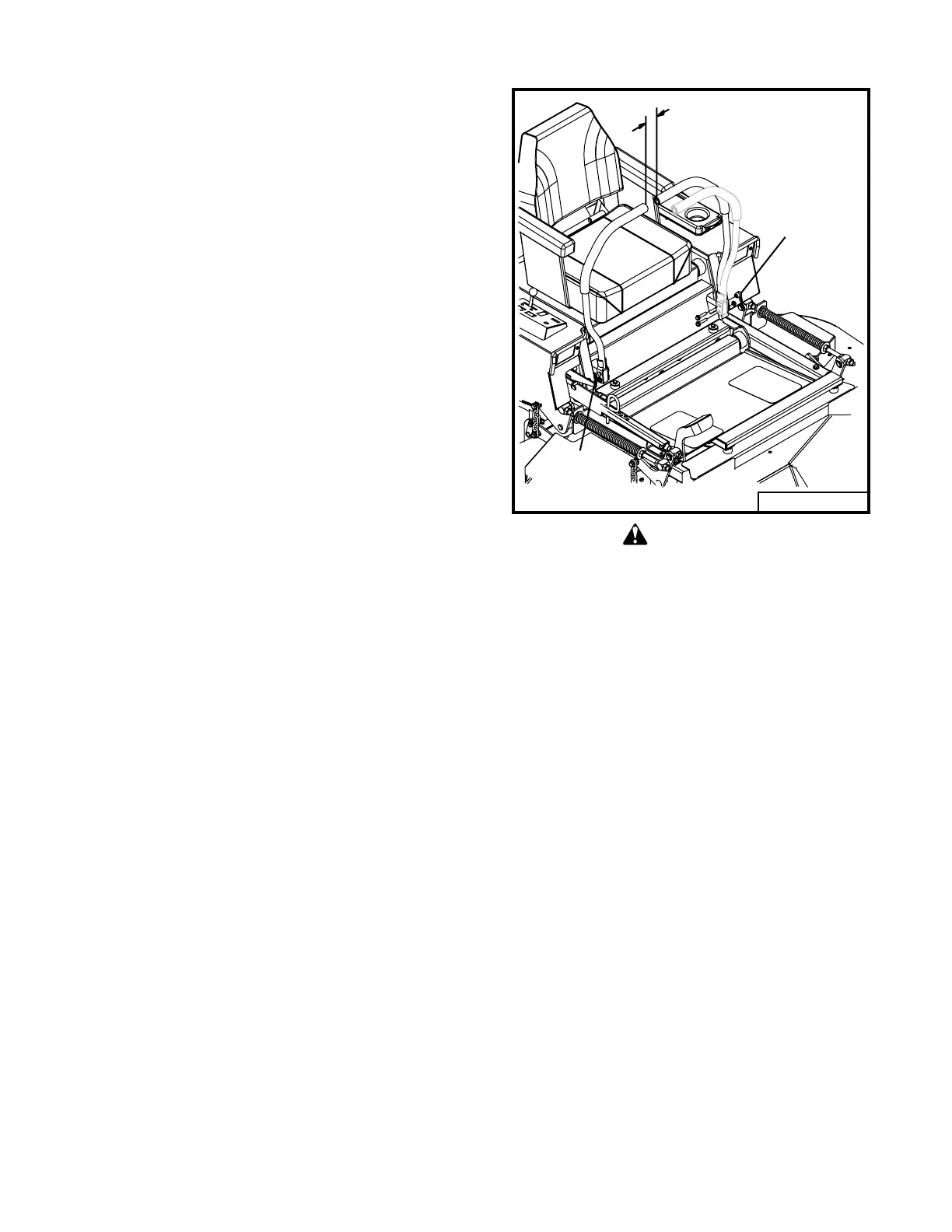
STEERING LEVER ADJUSTMENT
(Refer to Fig. 13)
Steering levers are secured to the lever mount
blocks with mounting bolts. The top bolts are
fastened with adjustable (lever) nuts. Adjustable
nuts can be tightened (clockwise) or loosened
(counterclockwise) without a tool. Adjustable
nuts can be ratcheted by pulling out on the lever
and rotating to a new position.
To adjust steering lever position, loosen nut on
the top mounting bolt. In the swung in (neu-
tral) position, the lever can now move
forwards and backwards without moving the
lever mount. If the lever mount moves with the
steering lever, the bottom mounting bolt may
need to be loosened. Set both levers in line
and in a comfortable position for the operator.
Move levers to the swung out (neutral lock)
position and tighten top nuts and bottom nuts if
loosened. Both mounting bolts MUST be tight
to assure steering lever control of the machine.
Steering levers must line up in the swung in
(neutral) position. Maintain one inch minimum
clearance between ends of levers. If the levers
are allowed to lean toward the center when the
mounting bolts are tightened, free play in the
mounting holes may allow the levers to hit each
other.
When completing a maintenance
function, make sure all shields are in
good condition and are installed before
placing unit back into use.
ENGINE TROUBLESHOOTING
Should you experience trouble in starting the en-
gine, use the following guide to locate possible
causes.
Engine will not crank:
n Battery is discharged.
n Blown starter fuse.
n PTO switch in “ON”.
n Steering levers are not out in neutral.
n Steering lever switches are out of adjustment
(listen for the switch “click”).
n A loose wire or connection.
Engine cranks, but will not start:
n Fuel tank is empty.
n Restricted fuel line or fuel filter.
n A loose wire or connection.
If the above points do not locate the problem, con-
tact your authorized Grasshopper dealer for repair.
1" minimum
Adjustable
Nut
Adjustable
Nut
99093