28
ADJUSTMENTS AND TROUBLESHOOTING
CAUTION
CAUTION
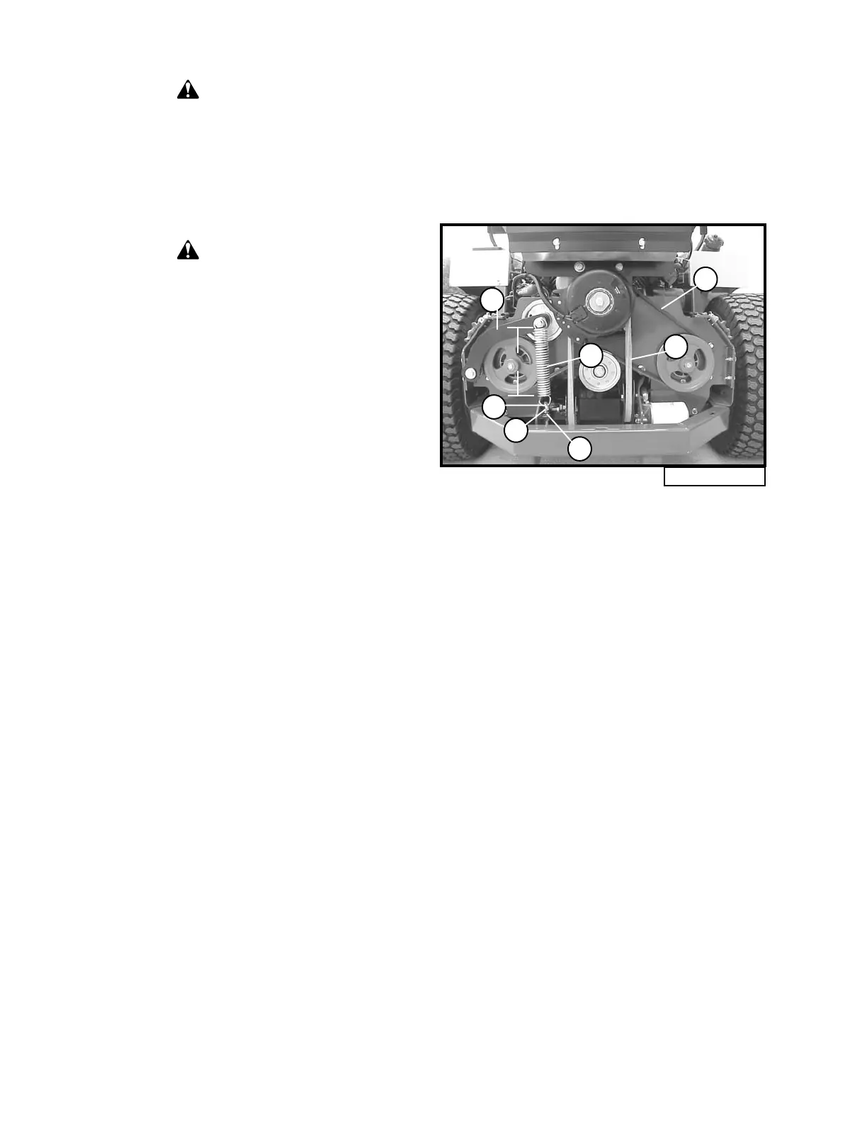
Fig. 12
B
A
F
G
D
C
E
5.75"
Always make adjustments with the
machined parked on a hard level
surface; with the engine stopped and
the PTO disengaged; with the park
brake set; and with the key removed
from the ignition.
Always remove the grounded (-)
clamp from the battery when
performing maintenance on the
engine, clutch, or any other electrical
system. To access battery, remove
the left fender.
LOSS OF POWER IN THE G
1
DRIVE
SYSTEM
Check the fluid level and make sure the proper
amount of fluid is in the reservoir. Make sure all
hydraulic connections are tight and not leaking.
Make sure drive belt is tight and not slipping.
Check park brake adjustment. Make sure pump
dump valve is tight so pump does not freewheel.
G
1
DRIVE BELT REPLACEMENT
(Refer to Fig. 12)
1. Remove the rear shield (page 41, item 44) by
unlatching the two rubber draw latches on
top and pulling the shield up and out.
2. Remove the mule drive belt (A) as described
in “Mule Drive Belt Removal” section (page
31).
3. Loosen the top locknut (C) and back off
(counterclockwise) the bottom drawnut (D)
to the end of the J-bolt (E), so that tension is
minimal in the idler spring.
4. Pull on idler arm (F) to extend idler spring
(G) and remove the belt (B) from pulleys.
5. Install the new belt with the idler tension
loose in the same manner.
6. To adjust the belt tension, loosen the top
lock nut (C) on the J-bolt. Adjust the lower
draw nut (D) so that the idler spring is ex-
tended to a length of 5.75 inches. Tighten
the top lock nut against the bracket.
7. Install the mule drive belt as described in
“Mule Drive Belt Installation” section (page
32).
8. Check belt tension after unit has run for ten
(10) hours.
NO POSITIVE NEUTRAL POSITION
If drive wheels travel forward or backward when
the steering lever is in swing-out position (neu-
tral), adjustment is required.
NEUTRAL ADJUSTMENT
(Refer to illustration on page 42)
1. Block up under tractor frame so both drive
wheels are off the ground.
2. Make sure parking brake is released.
3. Remove linkage rod (item 4) and damper
(item 34) from hydro pump control arm
(item 10).
4. Place steering levers in the neutral swing-out
position and start engine.
5. If either of the drive wheels turn, proceed
with the following adjustment.
6. Loosen locking nut (item 16) and rotate
pivot bolt (item 14) until neutral is achieved.
Tighten locking nut.
NOTE: Pivot bolt roller is mounted off cen-
ter and works as an eccentric when the bolt is
turned.