36
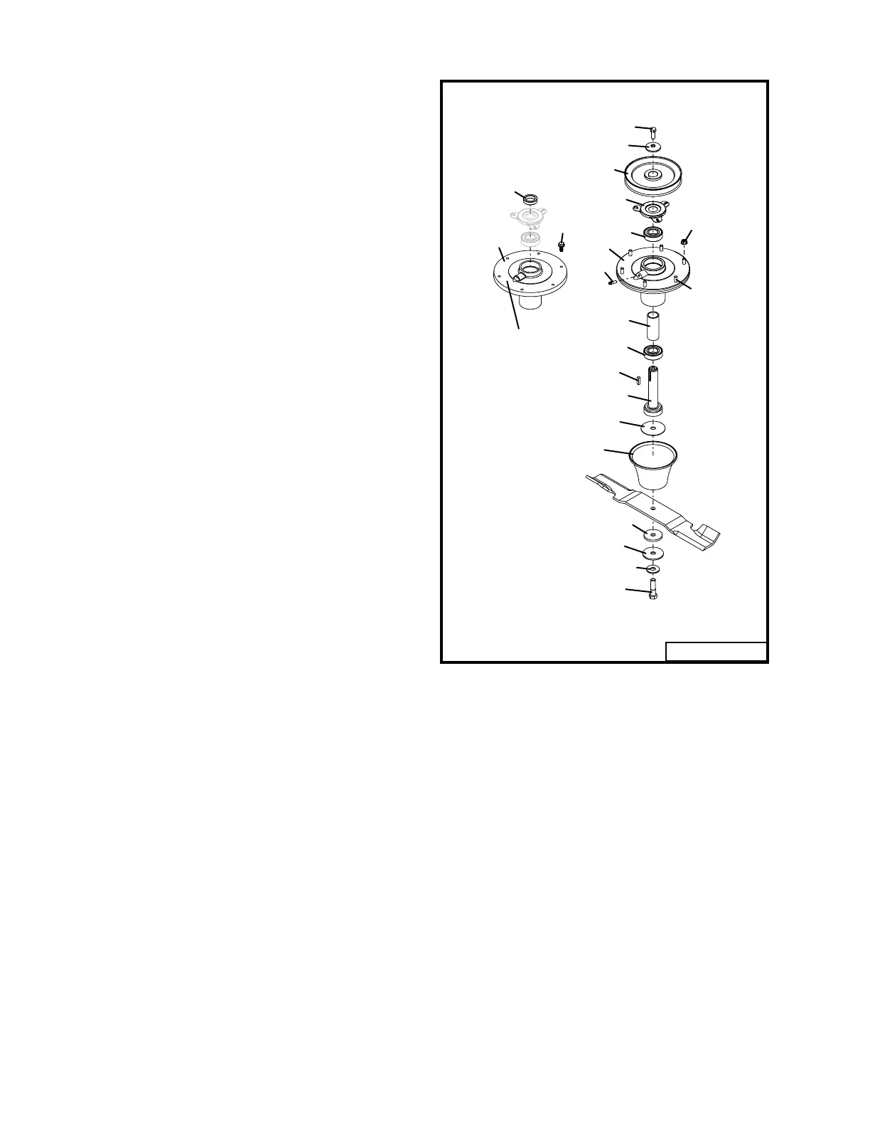
Fig. 26
BLADE SPINDLE ASSEMBLY
REPAIR/REPLACEMENT
(Refer to Fig. 26)
1. Remove blade spindle assembly as de-
scribed previously.
2. Press spindle shaft (9) down through bear-
ings (5) and spindle housing (6 or 20).
3. Press bearings (5) out of housing (6 or 20) or
remove from shaft (9) as necessary.
4. Visually inspect parts for excessive wear,
corrosion, or damage. Feel parts and rotate
bearing races to check for rough spots or ex-
cessive wear.
5. Replace with new parts as necessary.
6. Install lower bearing (5) on spindle shaft (9).
7. Install bearing spacer (8) on shaft.
8. Install this assembly into housing (6 or 20).
9. Press top bearing (5) onto shaft (9) down
against bearing spacer (8).
10. Rotate assembly to make sure shaft moves
freely.
11. Secure spindle assembly to the mower deck
with the six nuts or bolts (17 or 19). Torque to
21 ft. lbs.
12.Install bearing shield (4), .375" spacer (21)
(used on M172 deck only), square key (16),
sheave (1), cup washer (3) and bolt (2) in
same sequence as removed. Place a block
under the spindle shaft (9) if necessary to
hold it up in the spindle housing.
13.Make sure the concave side of the cup
washer (3) is down toward the sheave and
torque top bolt (2) to 38 ft. lbs.
14. Rotate assembly to check for free move-
ment.
15. Install deck belt and belt shields.
16. Install blade and tighten bolt (13) to 50-55 ft.
lbs.
Rev. 10-08
1
2
3
4
5
6
7
8
5
9
10
11
12
13
14
15
16
17
18
USED ON
M172
19
20
04107D
21