34
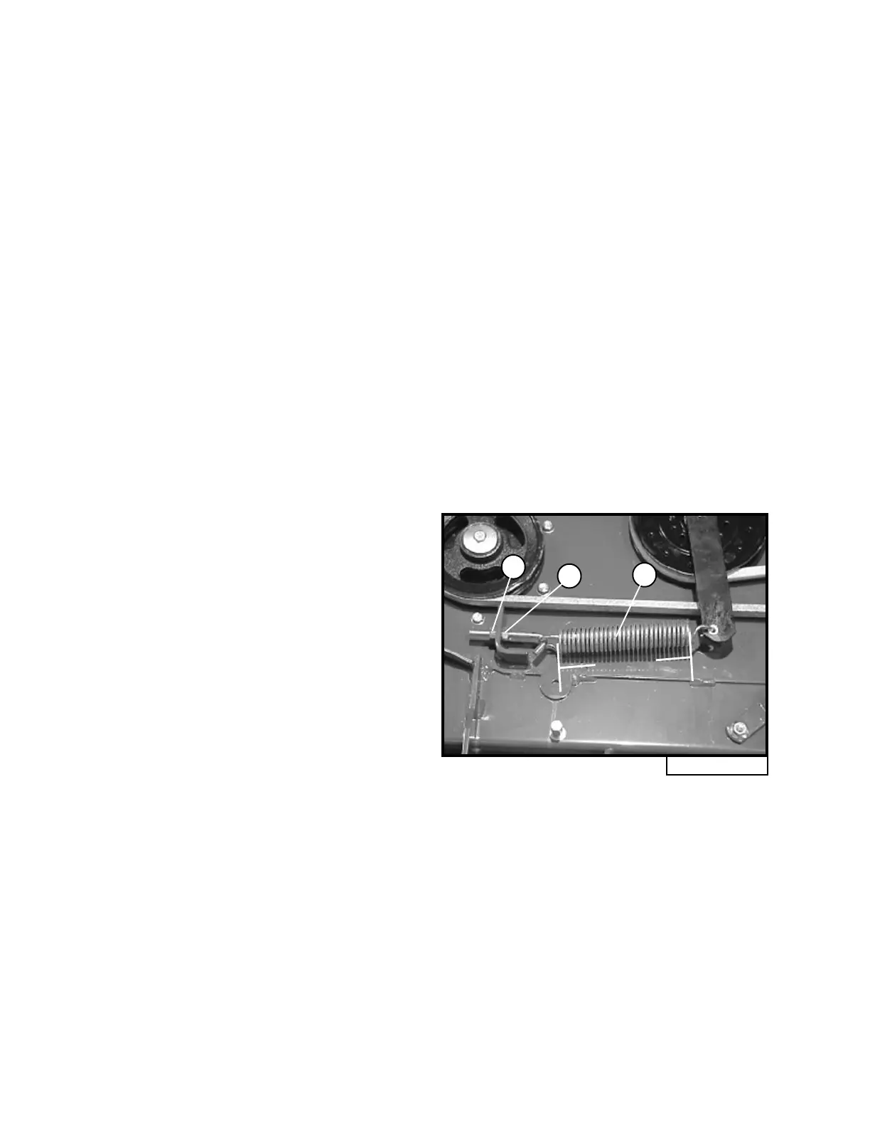
Fig. 24
C
A
B
5.75"
MOWER DECK CUT HEIGHT
SETTING ADJUSTMENT
(Refer to page 33, Fig. 23)
NOTE: Adjust side to side and front to rear
mower level before adjusting cut height.
1. Check air pressure on all four tires and adjust
to the correct pressure if necessary.
2. With foot lever (E), raise the mower deck
slightly and remove the cut height adjust-
ment pin (F) and place the cut height
adjustment pin in the hole for three inch cut
height. Release pressure on the foot lever
and allow the mower deck to lower until the
pin (F) contacts the latch tube guide (G).
Make sure the .25 inch deck height spacer
(H) is not between the cut height adjustment
pin and the latch tube guide.
3. Position left blade in the side to side position
and measure from the outside blade tip to the
level surface (refer to Fig. 22).
4. Position right blade in the side to side posi-
tion and measure from the outside blade tip
to the level surface.
5. If the difference between both measure-
ments is greater than .125 inch, side to
side adjustment is necessary (see appro-
priate section on page 32).
6. If both measurements are between 2.875 inches
and 3.125 inches, adjustment is not necessary.
7. If both measurements are less than 2.875 inches
or greater than 3.125 inch, adjustment is neces-
sary.
8. Loosen the jam nut (K) on the deck height set-
ting tube assembly (J).
9. Adjust the mower deck up to match the
height setting by turning the hex nut (L)
clockwise.
10. Adjust the mower deck down to match the
height setting by turning the hex nut (L)
counter-clockwise.
11. With blade cut height correct on both sides,
securely tighten the jam nut (K) on the deck
height setting tube assembly (J).
12. Make sure deck latch (M) still engages in
upper most position.
DECK BELT ADJUSTMENT
(Refer to Fig. 24)
The belt tension is set at the factory, but may
need adjustment after the first hour of initial use.
Periodically belt should be checked for proper
tension, following the procedure below:
1. Position the mower deck in the lowest (1
inch) cut height setting and remove the left
belt shield.
2. Loosen the lock nut (A) and adjust the draw
nut (C) to change belt tension.
3. Increase belt tension by turning the draw nut
(C) clockwise and decrease belt tension by
turning the draw nut counterclockwise.
4. The idler spring (B) body length should
measure approximately 5.75 inches for
proper belt tension.
5. Tighten the lock nut (A) when the proper
belt tension is achieved.
6. Re-install the left belt shield.