30
0
10
20 30
40
50
99098
Safety
Switch
Fig. 14
IMPORTANT
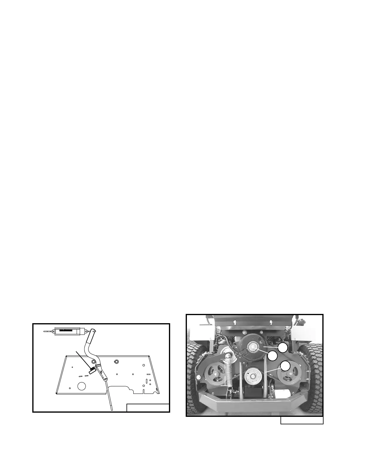
Fig. 15
B
A
5.75"
C
PARK BRAKE ADJUSTMENT
(Refer to illustration on page 45 and Fig. 14)
1. Adjust the right and left brake individually.
2. Disconnect the right brake linkage rod (item
16).
3. Adjust the linkage rod (item 16) attached to
the left brake until it takes 12 lbs. of pull at the
top of the hand lever to apply the parking brake.
Adjustment of the main brake linkage rod (item
26) may also be required.
4. Connect the right brake linkage.
5. Disconnect the left brake linkage rod (item
16).
6. Adjust the linkage rod (item 16) attached to
the right brake until it takes 12 lbs. of pull at
the top of the hand lever to apply the parking
brake.
7. Connect the left brake linkage.
8. With both brakes connected it should take
24 lbs. of pull at the top of the hand lever to
apply the parking brake.
9. Adjust the main brake linkage rod (item 26)
if necessary.
10. Be sure all cotter pins and jam nuts are se-
cured.
11.Make sure the brake light is on when the
park brake is set. If the brake lever does not
contact the safety switch, adjust the switch
in the mounting slots so it does.
CLUTCH/BRAKE BURNISHING
A new clutch, or one that has not been
used for three months, will require
burnishing to dress drive surfaces. The
clutch could fail if you do not
accomplish the following procedure.
Place tractor in neutral, start engine and run at
half throttle. Turn clutch switch on 30 seconds
and off 30 seconds, five times at half-throttle and
repeat five times at full throttle. The time interval
allows the clutch surface to cool.
CLUTCH REMOVAL/
REPLACEMENT
(Refer to Fig. 15)
1. Remove the rear shield (page 41, item 44) by
unlatching the two rubber draw latches on top
and pulling the shield up and out.
2. Remove the mule drive belt (A) as described
in “Mule Drive Belt Removal” section.
3. Remove the center bolt (B) and slide the
clutch (C) off the engine crankshaft.
4. To install clutch, reverse order and install
mule drive belt as described in “Mule Drive
Belt Installation” section.
5. Tighten center bolt (B) to 50 ft lbs.