31
Fig. 16
Fig. 17
Fig. 18
A
B
C
D
E
G
5.25"
C
F
A
A
B
C
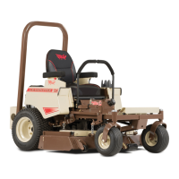
MULE DRIVE BELT ADJUSTMENT
(Refer to Fig. 16 & 17)
1. Position the mower deck in the transport (all
the way up) position and remove the rear
shield (page 41, item 44) by unlatching the two
rubber draw latches on top and pulling the
shield up and out.
2. Check that the mule drive belt (A) is routed
properly and has only 1/4 twist (B) between
the clutch pulley and each idler pulley (C &
D).
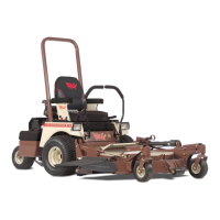
3. On a new mower with a new belt, the right
fixed idler pulley (D) is positioned in the top
of its mounting slot (E). The spring (F) on
the left idler pulley is extended to an ap-
proximate body length of 5.25 inches.
4. To tighten the belt, loosen the nut (G) on the
right fixed idler pulley (D). Slide the pulley
down in the slot and retighten.
5. To loosen the belt, loosen the nut (G) on the
right fixed idler pulley (D). Slide the pulley up
in the slot and retighten the pulley nut.
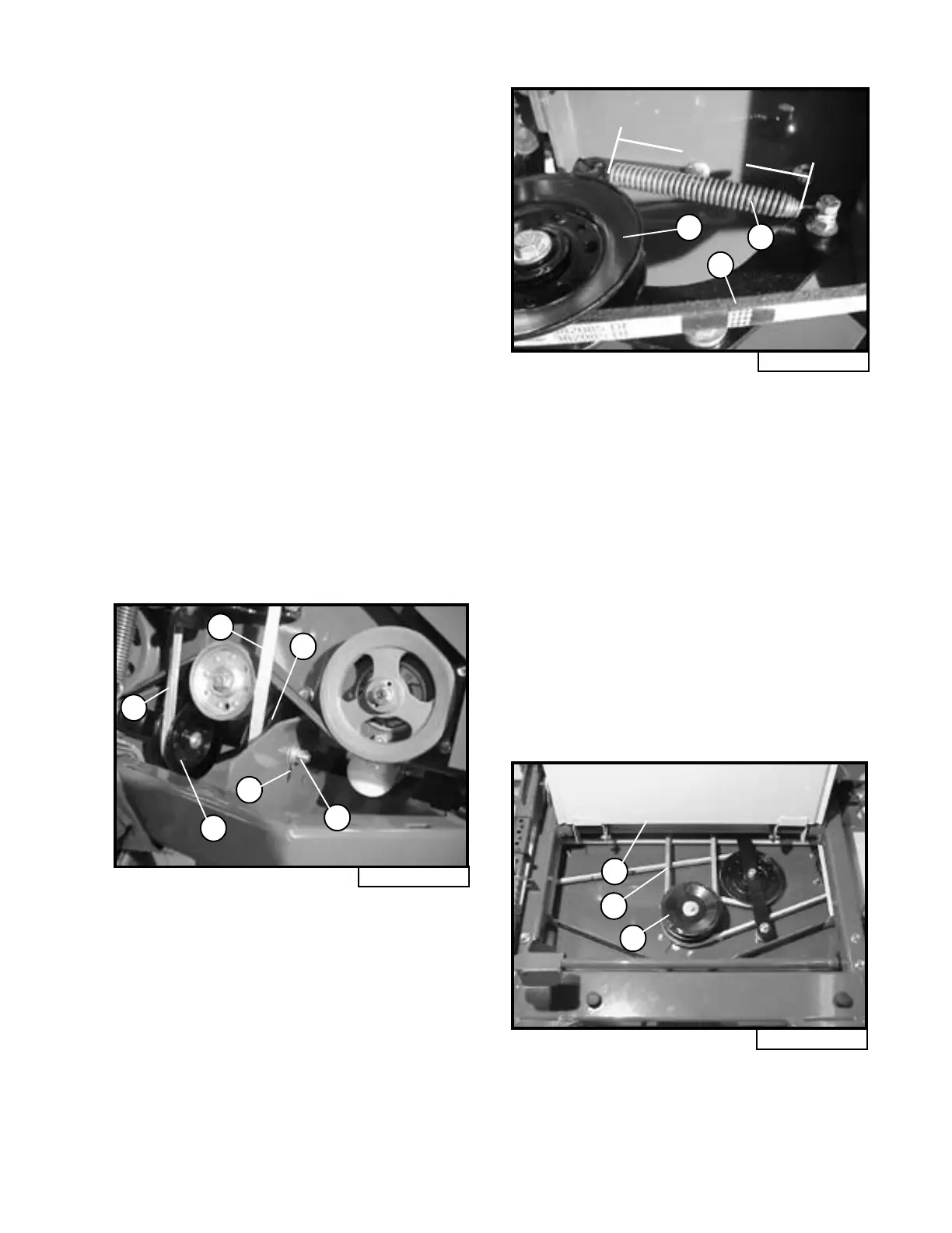
MULE DRIVE BELT REMOVAL
(Refer to Fig. 18 & page 32, Fig. 19)
1. Rotate the footrest plate (A) up until it
rests against the seat. Remove the rear
shield (page 41, item 44) by unlatching the
two rubber draw latches on top and pulling
the shield up and out.
2. Pull on the mule drive belt (B) on one side of
the deck drive pulley (C) and roll the belt off
the pulley.
3. Unplug wire harness from the clutch terminal
(H).
4. The mule drive belt can now be pulled off the
top of the clutch pulley and off the machine
from the rear.