106
Program description: Mixers
Asymmetrical mixer ratios
For many applications we need to set up different mi-
xer values on either side of the mixer neutral point.
If you select the ASY fi eld and (in our example) move
the elevator stick in one direction, the mixer ratio for
each direction of control can be set separately:
L i n e a r - M I X 2 E L 6
M i x i n p u t O f f s e t
+ 2 5 % + 5 0 % 0 %
®
O U T P U T
-
+
1 0 0
S T OA S YS Y M C L R
Note:
If you are setting up a switch channel mixer of the “S
NN” type you must operate the assigned switch to
achieve this effect. The vertical line then switches bet-
ween the left and right sides.
Setting the fi ve-point curve mixers 5 and 6
These two curve mixers enable you to defi ne extre-
mely non-linear mixer curves by placing up to three
(freely positionable) points between the two end-
points “L” (low = -100% control travel) and “H” (high =
+100%) along the control travel.
If you have already read the description of the
»Channel 1 curve« menu, or the method of program-
ming fi ve-point curves in the »Helicopter mixer«
menu, you can skip the following description.
Programming in detail
The control curve is defi ned by up to fi ve points,
known as “reference points”. In the basic setting three
reference points are already defi ned: the two end-
points “L” and “H” and point “1”, which is exactly in the
centre of the curve – see next illustration.
The following section applies to “any” mixer to which
we wish to assign a non-linear curve characteristic.
The examples shown in the following section are
only intended for demonstration purposes, i.e.
they do not represent realistic mixer curves.
C u r v e M I X 5 8 1 0
I n p u t - 4 5 %
C u r v e O u t p u t 0 %
o f f P o i n t
?
®
O U T P U T
-
+
1
1 0 0
Setting and erasing reference points
When you move the transmitter control assigned to
the mixer input – in this case function 8 – a vertical
line in the graph moves in parallel between the two
end-points. The current stick position is also displayed
in numeric form in the “input” line. The point at which
this line coincides with the current curve is termed the
“output”, and this point can be varied within the range
-125% to +125% by setting the reference points (see
below). This control signal acts upon the mixer output.
In the example above the stick is at -45% travel, but
the output signal is still 0%.
Between the two end-points “L” and “H” a maximum
of three reference points can be set with a minimum
spacing of about 30% control travel. Move the stick,
and a brief press on the rotary control fi xes an additi-
onal reference point at the crossing point with the cur-
rent control curve as soon as the inverse video ques-
tion mark is visible. The order in which you genera-
te the additional points is unimportant, as all the refe-
rence points are automatically re-numbered sequenti-
ally from left to right.
Example:
C u r v e M I X 5 8 1 0
I n p u t - 4 5 %
C u r v e O u t p u t 0 %
o f f P o i n t
?
®
O U T P U T
-
+
1
1 0 0
2
With the transmitter control in this position you could
now defi ne the third reference point between “L” and
“H”.
If you wish to erase one of the set reference points
between “L” and “H”, move the stick to the reference
point in question. The reference point number and the
associated reference point value (“OUTPUT”) are dis-
played in the “Point” line. Press the CLEAR button to
erase the point. Note that the reference points “L” and
“H” cannot be erased.
Note:
For technical reasons the control travel of the two sli-
ders in the centre console may be limited to less than
+/-100%. In this case you may need to increase the
control travel in the »Control adjust« menu in order
to set points “L” or “H”.
Changing the reference point values
To change the reference point values move the stick
to the reference point to be varied: “L, 1 ... 3 or H”.
The screen displays the number of this point and its
current curve value. Place the rotary control in the in-
verse video fi eld, and you can change the current cur-
ve value within the range -125% to +125%, without
affecting the adjacent reference points.
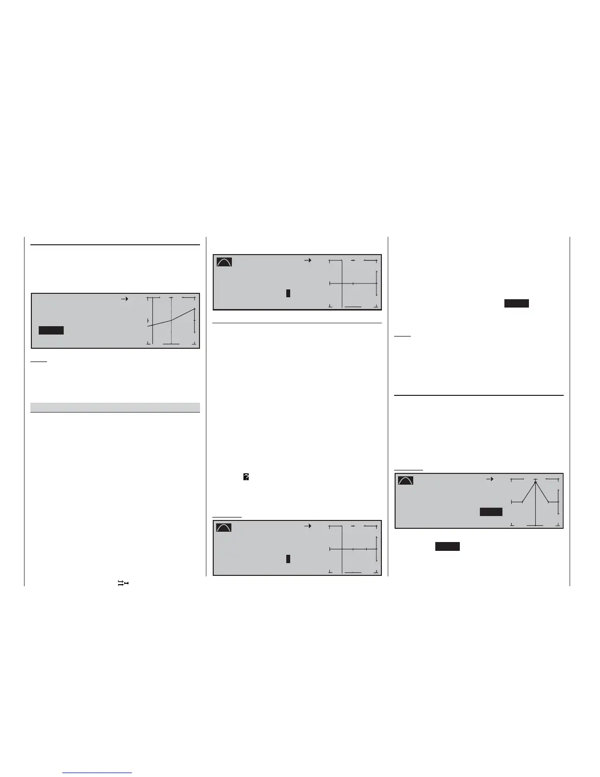
Example:
C u r v e M I X 5 8 1 0
I n p u t + 0 %
C u r v e O u t p u t + 9 0 %
o f f P o i n t 2
+ 9 0 %
®
O U T P U T
-
+
2
1 0 0
1
3
In this example reference point “2” is set to +90%.
Pressing the CLEAR button erases the marked refe-
rence point.