Page
interchange the outputs.
Exception: Fail-Safe is always defi ned with reference to the receiver sockets.
• Model type Motor: Direction of effect of Ch1 function, throttle minimum “back”, “forward” or “none”. The Ch1
trim acts only “back”, “forward” or over the full range respectively.
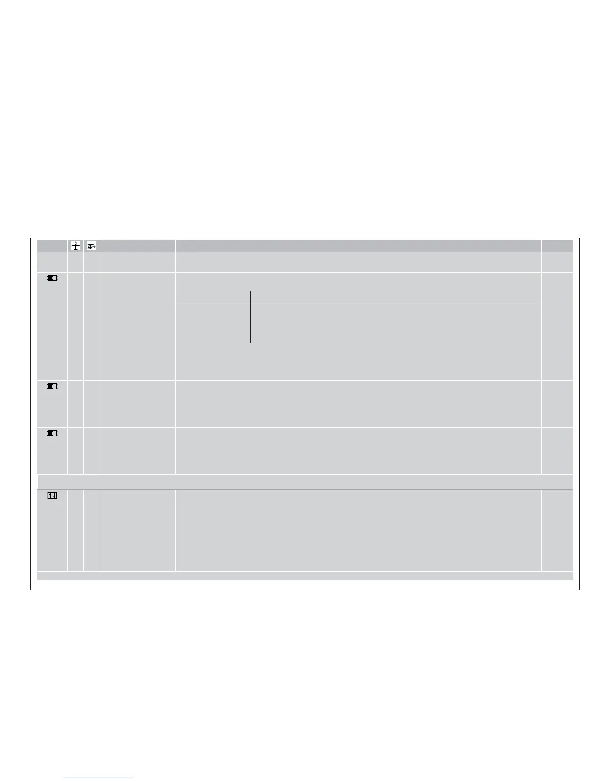
Tail type Servo count
„normal“
“V-tail”
“Delta / fl ying wing”
„2 Elev. Sv 3+8“
Optionally up to two aileron servos and up to two fl ap servos
Optionally up to two aileron servos and two fl ap servos
Two elevon servos and up to two fl ap servos
Two elevator servos, plus optionally up to two aileron servos and two fl ap servos
Brake: The wing mixers “brake 5 aileron”, “brake 6 fl ap” and “brake 3 elevator” can opti-
onally be controlled by a transmitter control connected to “input” 1, 8 or 9. Variable mixer
neutral point (offset). If the neutral point is not set at the end of travel, the remaining travel
is a dead zone.
52
• Helicopter type Swashplate type: Select the number of servos (1 ... 4) for collective pitch
Rotor direction: “right” (clockwise) or “left” (anti-clockwise) as seen from above
Coll. pitch min.: Minimum collective pitch angle, channel 1 control “forward” or “back”, see also »Basic
settings« menu.
Expo throttle limit: “Throttle limit” can be set to exponential in »Control adjust« menu.
53
• • Servo adjustment Servo direction: Left or right
Neutral setting: Offset centre point within range -125% to +125%
Servo travel: Symmetrical or asymmetrical, range 0 to 150%
Servo travel limit: Symmetrical or asymmetrical, range 0 to 150%. Typical application: if servo travel is me-
chanically restricted.
56
Transmitter controls
• Control adjust Assignment and de-coupling (display = “free”) of transmitter controls (rotary control, sliders, switch modules) 5
to 10. Inputs 5 ... 8 are programmable separately for each fl ight phase. External switches, control switches or the
fi xed switch “FX” can also be assigned if required. Note: two external switches at one input correspond to the
function of the GRAUPNER 2-channel switch module, Order No. 4151 or 4151.1.
Travel: Variable control travel, symmetrical or asymmetrical between -125% and +125%; direction of control’s
effect can also be reversed.
Offset: The centre point of the transmitter control can be offset within the range -125% to +125%
Time: Symmetrical or asymmetrical reduction of transmitter control transit speed. Available range: 0 ... 9.9
sec., e.g. for scale processes, “soft” motor acceleration, etc..
58