Note
4159
2 / 16-channel
NAUTIC-Expert
switch module
For each 16-
channel NAUTIC-
Expert module in
the transmitter,
one 2 / 16 chan-
nel NAUTIC Ex-
pert switch modu-
le is required.
4142N
NAUTIC Multi-
Prop decoder
Four servos can
be connected
3941.6
Flat socket with
3-core lead
For connecting
consumer units
drawing up to 0.7
A per switched
channel
3936.11
or
3936.32
Y-lead, cable
length 110 mm
or 320 mm
For connecting
NAUTIC switch
modules or re-
verse modules
3754.1
NAUTIC switch
module
Direct connection
of two modules
via synchronous
distributor
3754.2
NAUTIC re-
verse module
Parallel connec-
tion to two chan-
nels or to one
channel via syn-
chronous distri-
butor
Specifi cation, NAUTIC Expert switch module,
Order No. 4159
Current drain approx. 3 mAh
Dimensions approx. 69 x 42 x 20 mm
Weight approx. 47 g
Specifi cation, NAUTIC Multi-Prop decoder, Or-
der No. 4142N
Current drain approx. 10 mAh
Dimensions approx. 69 x 42 x 20 mm
Weight approx. 27 g
Connecting equipment to the NAUTIC Expert
module at the receiver
Each switch module can operate up to sixteen
switched functions.
The module can be connected directly to eight
electrical consumer units, such as fi lament bulbs,
LEDs etc. – but not electric motors – with a cur-
rent drain of up to 0.7 A each. See Fig. 1 for batte-
ry connection.
Two switched functions per socket are possible
using the three-core lead, Order No. 3941.6. See
Fig. 2.
NAUTIC switch or reverse modules are available
for electric motors and other electrical consumers
drawing higher currents. See Figs. 3 + 4.
To obtain a forward – stop – reverse function, con-
nect the reverse module to the Expert switch mo-
dule using the synchronous distributor lead, noting
that one plug attached to the reverse module must
be connected the “wrong” way round: fi le off the
edges of the plug slightly to permit this.
An external power supply is required for directly
connected electrical consumer units and for swit-
ching relays, e.g. a GRAUPNER receiver batte-
ry of adequate capacity. Other batteries up to max.
30 V can be connected using the connecting lead,
Order No. 3941.6. In this case take particular care
to maintain correct polarity:
red wire = positive (+)
brown wire = negative (–).
Fig. 1
Battery connection via
adaptor,
Order No. 3941.6
+
–
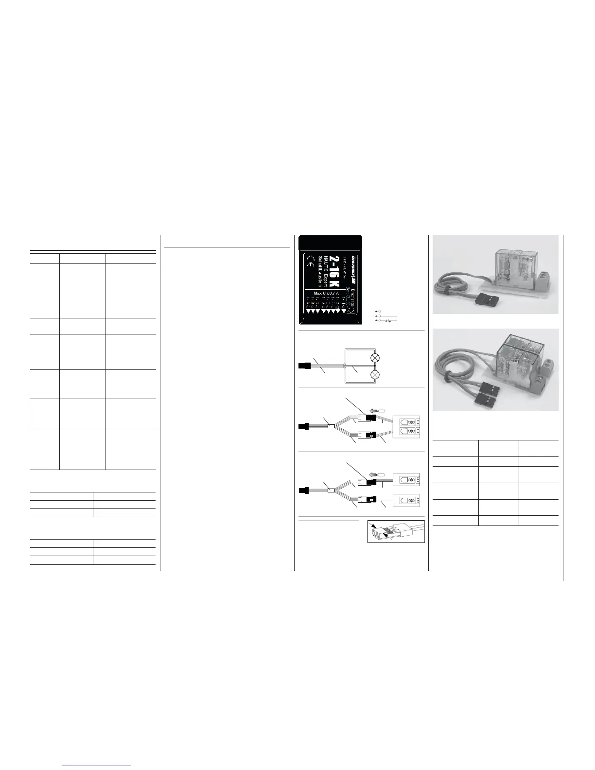
Nautic switch module, Order No. 3754.1
Nautic reverse module, Order No. 3754.2
Specifi cations
Switch modu-
le 3754.1
Reverse mo-
dule 3754.2
Exciter voltage 4,8 ... 12 V 4,8 ... 12 V
Max. switched
current
16 A 16 A
Max. switched
voltage
24 V 24 V
Dimensions in
mm approx.
50 x 27 x 26 50 x 30 x 26
Weight approx. 25 g 45 g
Fig. 2
Fig. 3
Fig. 4
Three-core lead with fl at socket,
Order No. 3941.6
Consumer unit,
max. 0,7 A
Consumer unit,
max. 0,7 A
brown
orange
red
NAUTIC reverse
module,
Order No. 3754.2
orangeorange
orange red
Y-lead,
Order No. 3936.11
NAUTIC switch
module,
Order No. 3754.1
Connect lead with
reversed polarity*
Connect lead with
reversed polarity*
Y-lead,
Order No. 3936.11
orangeorange
orange
red
* Bevel edges of plug
as shown
free