34
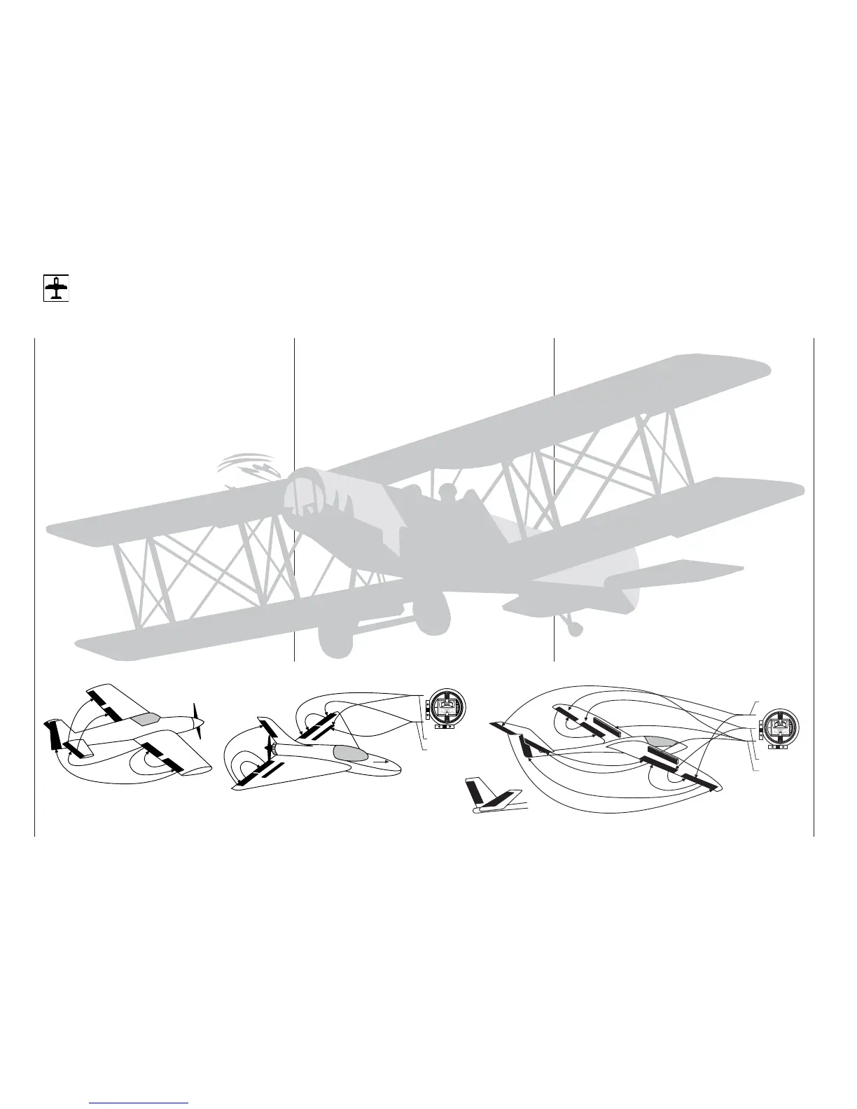
Fixed-wing model aircraft
Fixed-wing models
This program provides straightforward, carefully tailo-
red support for conventional models with up to two ai-
leron servos and two fl ap servos, models with V-tail,
fl ying wings and deltas with two elevon (aileron / ele-
vator) servos and two fl ap servos. The vast majority of
power models and gliders belong to the “normal” tail
type with one servo each for elevator, rudder, ailerons
and throttle (or electronic speed controller, or airbra-
kes on a glider). There is also the special model type
“2Elev.Sv3+8” which provides a means of connecting
two elevator servos to channels 3 and 8.
If the model has a V-tail instead of a standard tail con-
fi guration, you should select the “V-tail” type in the
»Model type« menu, as this mixes together the ele-
vator and rudder functions in the required way, i.e.
each tail control surface is actuated by a separate
servo, and both assume superimposed elevator and
rudder functions.
If your model features two separate aileron servos,
the aileron travels can be set up with differential mo-
vement, i.e. the down-travel can be set independent-
ly of the up-travel. Finally the program caters for cam-
ber-changing fl aps which can be operated by the
transmitter control connected to socket “CH6”.
The “fl ap differential” function can be used to provide
differential travel when the fl aps are programmed to
follow the aileron function.
For deltas and fl ying wings it is easy to set up mixed
elevons, i.e. the aileron and elevator functions can be
carried out via single control surfaces at the trailing
edge of the right and left wing. The program contains
the appropriate mixer functions for the two servos as
standard.
Up to four fl ight phases can be programmed in each
of the thirty model memories (see »Phase settting«
and «Phase assignment« menus). A copy facility is
provided, making the setting of individual fl ight pha-
ses much easier (»Copy / Erase« menu).
Two timers are available at all times when fl ying. The
screen also displays the transmitter operating time
and the time which has elapsed for each model me-
mory.
The digital trim positions are stored separately for
each fl ight phase with the exception of the Ch1 trim.
The Ch1 trim provides a simple means of re-locating
the correct idle throttle setting.
“Dual Rate” and “Exponential” can be programmed for
aileron, rudder and elevator, giving two modes of con-
trol in each fl ight phase.
As an option, a transmitter control (rotary knob, slider
or switch module) can be assigned to inputs 5 ... 8 se-
parately for each fl ight phase (see »Control adjust«
menu).
In addition to four freely assignable linear mixers,
the program offers two curve mixers (»Free mixers«
menu), two dual mixers (»Dual mixers« menu) and
a fi ve-point curve (»Channel 1 curve«) for channel 1
(throttle / brake).
Depending on the model type you have selected, the
“Wing mixers” menu presents you with a list of pre-
defi ned mixers and coupling functions from which you
can choose:
1. Aileron differential
2. Flap differential
3. Aileron rudder (switchable),
4. Aileron fl ap (switchable)
5. Airbrake elevator (switchable)
6. Airbrake fl ap (switchable)
7. Airbrake aileron (switchable)
8. Elevator fl ap (switchable)
9. Elevator aileron (switchable)
10. Flap elevator (switchable)
11. Flap aileron (switchable)
12. Differential reduction
E
l
e
v
a
t
o
r
Õ
F
l
a
p
F
l
a
p
Õ
E
l
e
v
a
t
o
r
F
l
a
p
Õ
A
i
l
e
r
o
n
A
i
l
e
r
o
n
Õ
F
l
a
p
A
i
l
e
r
o
n
Õ
R
u
d
d
e
r
E
l
e
v
a
t
o
r
Õ
A
i
l
e
r
o
n
left
right
E
l
e
v
a
t
o
r
Õ
F
l
a
p
F
l
a
p
Õ
E
l
e
v
a
t
o
r
A
i
l
e
r
o
n
Õ
R
u
d
d
e
r
A
i
l
e
r
o
n
Õ
F
l
a
p
Airbrake
Õ
Flap
Airbrake
Õ
Elevator
Airbrake-Function 1
left
right
Rudder/Elevator
V-Tail
E
l
e
v
a
t
o
r
Õ
A
i
l
e
r
o
n
A
i
l
e
r
o
n
Õ
R
u
d
d
e
r
F
l
a
p
Õ
E
l
e
v
a
t
o
r
E
l
e
v
a
t
o
r
Õ
F
l
a
p
A
i
l
e
r
o
n
Õ
F
l
a
p
F
l
a
p
Õ
A
i
l
e
r
o
n
F
l
a
p
Õ
A
i
l
e
r
o
n
A
i
l
e
r
o
n
Õ
F
l
a
p
Airbrake
Õ
Flap
Airbrake
Õ
Elevato