30
Assigning external switches and control switches
Basic procedure, meaning of the fi xed switch “FX”
At many points in the program there is the option of
assigning a switch to a particular function, using an
external switch or a control switch (see below), or
using a switch to select one of two settings, e.g. cur-
ve settings, the DUAL RATE / EXPO function, fl ight
phase programming, mixers etc.. In all situations the
mc-22s allows you to assign several functions to one
switch, if you wish.
The process of assigning switches is exactly the
same in all the menus concerned, and we will explain
the basic programming procedure at this point so that
you can concentrate on the special features when
reading the detailed menu descriptions.
A switch symbol appears in the bottom line of the
screen at all programming points where switches can
be assigned:
If you move to this fi eld using the rotary control, the
switch symbol fi eld changes to inverse video (black
background):
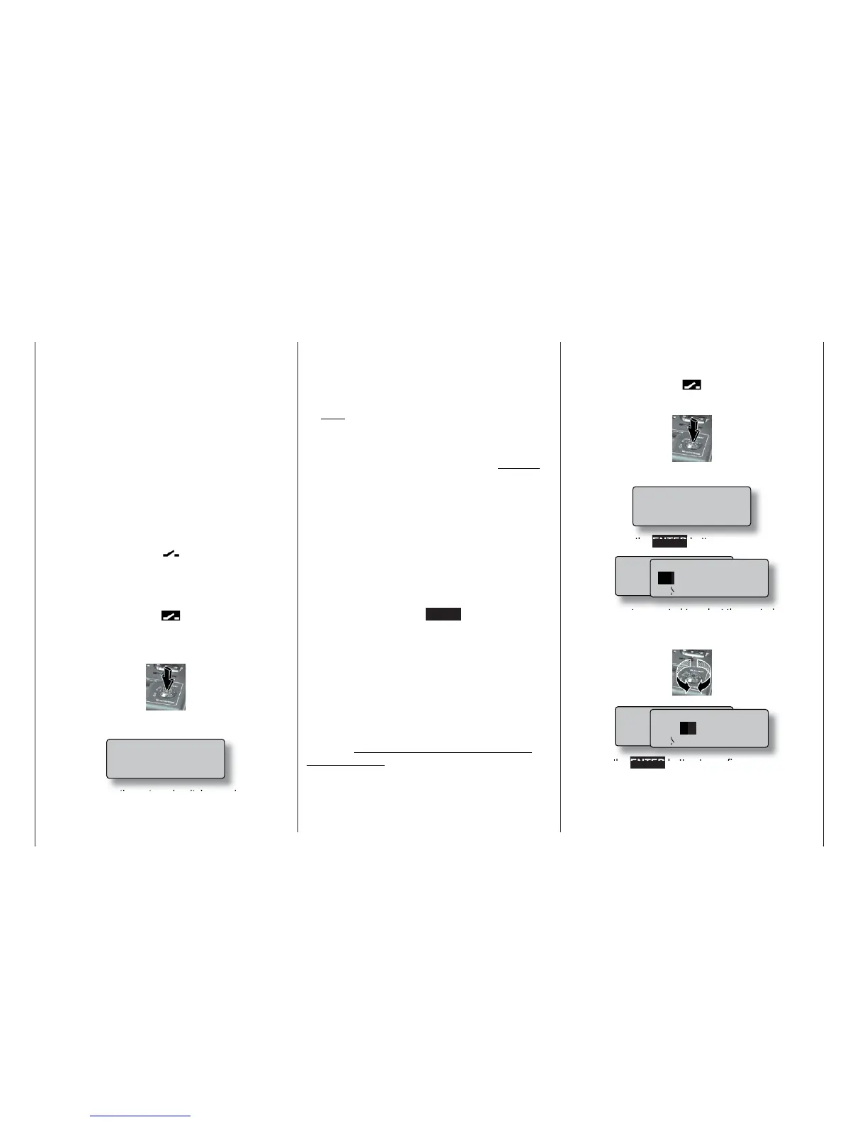
This is how you assign an external switch:
1. Brief press on the rotary control
2. The following fi eld appears on the screen:
Simply move the external switch you wish to
use to the “ON” position – regardless of the so-
cket number 0 ... 7 to which the switch is connec-
ted. This completes the assignment process; the
switch concerned (external or control switch) now
appears in the appropriate menu. A switch symbol
adjacent to the switch number indicates the cur-
rent state of the switch concerned.
Note:
The position to which you eventually move the
switch (in order to assign it) is accepted by the
transmitter as the ON position. For this reason you
should move the external switch to the preferred
OFF position before you activate the switch sym-
bol.
3. Changing the direction of switching
If the switch turns out to work in the wrong direc-
tion, correct it as follows: move the switch to the
desired OFF position, select the switch symbol
once more and assign the switch again, this time
with the direction of switching you prefer.
4. Erasing a switch
Activate the switch symbol as described under
point 2, then press the CLEAR button to erase the
switch.
Using transmitter control switches
For some special functions it may be preferable to
trigger the switching action at a particular (selectable)
position of a stick, slider or rotary knob (termed the
control position), rather than manually using a normal
external switch.
Four switches of this type, termed control switches
G1 ... G4, are available for this purpose. Note that the
number is simply the number of the control switch; it
does not indicate the number of the transmitter cont-
rol to which it is assigned, i.e. one of the control func-
tions 1 ... 4.
This is how you assign a control switch:
Start by selecting the switch symbol fi eld (inverse vi-
deo):
1. Brief press on the rotary control
2. The screen now displays the following fi eld:
Now press the ENTER button:
3. Use the rotary control to select the control switch
G1 ... G4 you wish to use, or a software “re-
versed” control switch G1i ... G4i (i - “inverted”):
4. Press the ENTER button to confi rm your selec-
tion, or press the rotary control briefl y.
Switch assignment
Move desired switch
to ON position
(ext. switch: ENTER)
M o v e d e s i r e d s w i t c h
o r c o n t r o l
( e x t . s w i t c h : E N T E R )
C n t r l / f i x e d s w i t c h
G 1
G 2 G 3 G 4 F X I
F X
G 1 i G 2 i G 3 i G 4 i
M o v e d e s i r e d s w i t c h
o r c o n t r o l
( e x t . s w i t c h : E N T E R )
C n t r l / f i x e d s w i t c h
G 1 G
2 G 3 G 4 F X I
F X
G 1 i G 2 i G 3 i G 4 i
Move desired switch
to ON position
(ext. switch: ENTER)