62
Program description:
Transmitter controls
Control adjust
Throttle limit function
Throttle limit: input 12 (throttle limit and Ch1 trim, throttle limit and expo throttle limit)
The meaning and application of “throttle limit”
In contrast to fi xed-wing model aircraft, the power
of a model helicopter’s motor or engine is not cont-
rolled directly using the Ch1 stick, but indirectly via
the throttle curve, which is set up in the »Helicopter
mixer« menu. (For separate fl ight phases you can set
different throttle curves using fl ight phase program-
ming; see pages 78 - 81).
Note:
If the model helicopter is fi tted with a speed governor
(regulator), this assumes control of motor output.
Generally speaking, the throttle servo does not move
anywhere near the idle position at any time during
“normal” fl ying – even if a governor is in use. This
means that the motor cannot be started, as the thrott-
le is too far open; nor can it be stopped reliably.
This is where the “throttle limiter” comes into its
own. In the Heli program, the “Throttle limiter 12” in-
put in the »Control adjust« menu is reserved for the
“Throttle limit” function. Using a separate transmitter
control – generally the right-hand slider – connected
to socket 7 on the transmitter circuit board, the positi-
on of the throttle servo (connected to receiver output
6) can be limited to any value. This means that the
“throttle” setting can be reduced right down to the idle
position. At the other extreme, the throttle servo can
only follow the throttle curve and reach the full-thrott-
le position if the throttle limit control is moved to the
point where full servo travel is released.
The value in the (right) “+” side of the “Travel” co-
lumn must therefore be set within the range 100% to
125%, to ensure that there is no chance that it will re-
strict the full-throttle setting available via the Ch1 stick
when the control is at its maximum position. The va-
lue on the left side of the “– Travel +” column should
be set in such a way that the throttle is closed com-
pletely when the digital Ch1 trim is also used, so that
you can reliably stop the motor. For this reason you
should leave the bottom value of the throttle limit sli-
der at +100%.
%NTER#NTR
%NTERFREE
4H,#NTR
OFFSETTRAVELTIME
3%,
L
!39
39-
!39
39-
3%,
%NTER#NTR
However, this variable “limiting” of the throttle travel
does not only provide a convenient method of starting
and stopping the motor; it also offers a convenient
method of recording fl ight times. To achieve this, all
you have to do is program a transmitter control switch
close to the full-throttle point of the throttle limit slider,
and then assign this to the timer to act as the On / Off
switch.
At the same time this arrangement provides a sig-
nifi cant additional level of safety. Just imagine what
might happen if, for example, you are carrying the he-
licopter to the take-off point with the motor running,
and accidentally move the Ch1 stick …
To avoid this danger, you will hear an audible warning
if the throttle is too far open when you switch on the
transmitter; at the same time the following message
appears on the basic display:
CAUTION:
Setting the “Throttle limit 12” input to “free” does
not switch the throttle limit function off; it just
sets the limiter to “half-throttle”.
Tip:
You can call up the »Servo display« menu to check
the infl uence of the throttle limit slider. Bear in mind
that servo output 6 controls the throttle servo on the
mc-22s.
Note:
If you connect a servo to output 12, it can be used in-
dependently for other purposes by means of mixers.
All you have to do is separate this servo from the
transmitter control connected to function input 12 in
the »MIX-only channel« menu; see page 108.
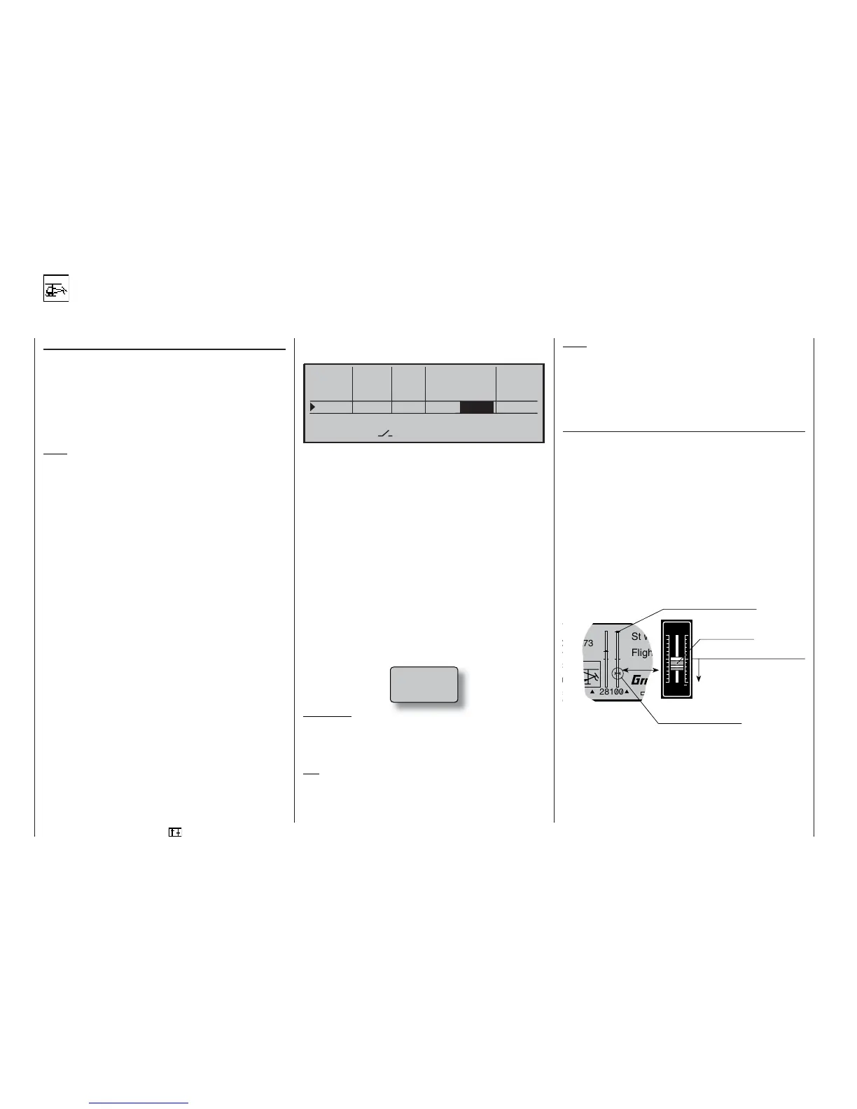
Throttle limit in conjunction with the digital trim:
When used with a throttle limit slider, the Ch1 trim
places a marker at the set idle position of the motor.
At this point the motor can be stopped using the trim.
If a second marker is set in its end-range (see dis-
play), then a single click immediately takes you back
to the marker, i.e. to the pre-set idle position – see
page 32.
The cut-off trim only acts as idle trim on the throttle li-
mit in the bottom half of the slider travel, i.e. the mar-
ker is only set and stored within this range.
Above the centre point the motor cut-off trim has no
effect; for this reason the corresponding display is
then suppressed.
For this reason: move the throttle limiter in the di-
rection of motor idle before you start the motor. The
throttle servo now only responds to the position of the
Ch1 trim lever, and not to the throttle / collective pitch
stick. Once the motor is running you should check
that the motor can also be stopped reliably using the
Ch1 trim lever.
Thr
too
high!