157
Module required at the transmitter
NAUTIC Multi-Prop module
Order No. 4141
(up to two modules can be installed)
Method of working
The NAUTIC Multi-Prop module expands one
standard control function to provide four func-
tions, i.e. three additional servo sockets are avai-
lable for each module at the receiver end. A maxi-
mum of two Prop modules can be installed in the
transmitter.
Requirements for connecting NAUTIC Mul-
ti-Prop modules to the function inputs CH8 ...
CH10:
1. The model memory to be used must fi rst be
erased using the “Erase model” option in the
»Copy / Erase« menu, and programmed to the
“Fixed wing” model type.
2. The transmitter and receiver must be set to
PPM18 or PPM24 transmission mode.
3. The control function selected must not be in
use simultaneously as the input channel or out-
put channel of any mixer, whether »Wing mi-
xers« or »Free mixers«.
4. In the »Control adjust« menu the settings of
the control channel to be used for NAUTIC pur-
poses must be left at the standard default set-
tings, or reset to that status using CLEAR.
5. The “servo travel” of the control channel to be
NAUTIC
NAUTIC multi-proportional modules
For the PPM18 and PPM24 transmission modes
used for NAUTIC purposes must be set SYM-
metrically to 150% in the »Servo adjustment«
menu and the “travel limit” left at 150%
or be
reset to this value using CLEAR.
6. Make sure that the direction of servo rotation
is standard (not reversed), and check that the
servo centre is at 0%.
(If one of the servos connected to the decoder at
the receiver end “jitters” slightly at full travel, adjust
the servo centre within a range of about -20% to
+20% until the jitter disappears.)
This completes the set-up procedure at the trans-
mitter.
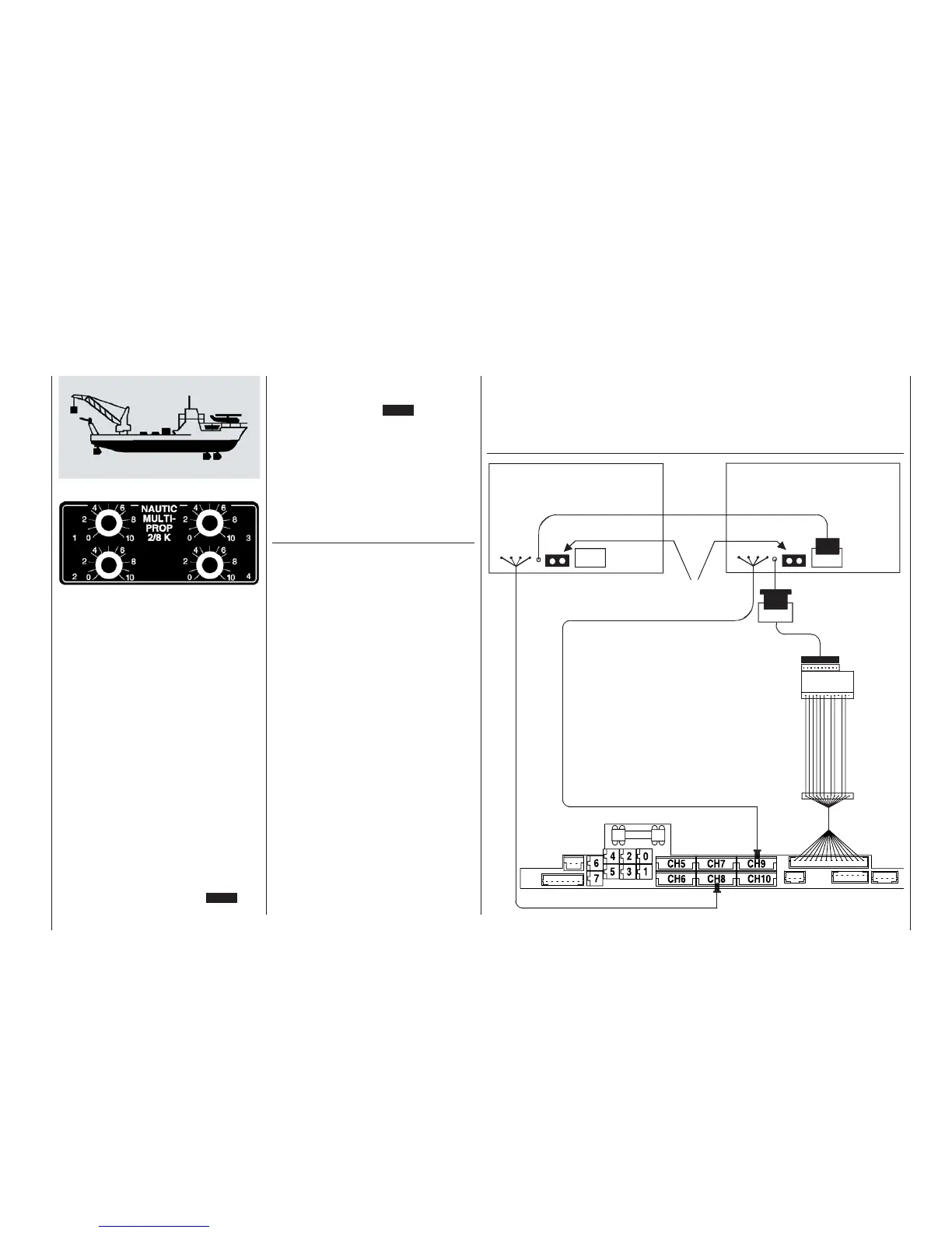
Installing and connecting NAUTIC modules in
the mc-22s transmitter
The modules are installed in vacant module wells
as described in the notes on page 15 of this ma-
nual. Connect the fi ve-pin plug to one of the so-
ckets CH8 to CH10 on the transmitter circuit
board, bearing in mind the requirements outlined
above.
Locate the four-pin plug which terminates the sin-
gle-core wire attached to the NAUTIC Multi-Prop
module, and connect it to the socket on the trans-
mitter circuit board using the interface distributor,
Order No. 4182.3, or the mc-22(s) / mc-24 adap-
tor, Order No. 4184.1, using the adaptor lead, Or-
der No. 4184.4.
The jumpers supplied with the adaptor lead must
be fi tted to the NAUTIC modules installed in the
transmitter.
If a second module is installed, locate the sing-
le-core wire terminating in a four-pin plug, and
connect it to the fi rst module, which is already in-
stalled.
mc-22s transmitter connections
NAUTIC-Multi-Prop module
Order No. 4141
NAUTIC-Multi-Prop module
Order No. 4141
Fit the jumpers!
NAUTIC adaptor
Order No. 4184.4
Adaptor, Order No. 4184.1
or
mc-22(s) interface distri-
butor, Order No. 4182.3
Transmitter interface