96
Although the throttle and collective pitch control sys-
tems are based on separate servos, they are always
operated in parallel by the throttle / collective pitch
stick (except when auto-rotation is invoked). The Heli-
copter program automatically couples the functions in
the required way.
In the software of the mc-22s the trim lever of control
function 1 only affects the throttle servo, e.g. as idle
trim (see Motor cut-off trim, page 32).
The process of adjusting throttle and collective pitch
correctly, i.e. setting the power curve of the motor to
match the collective pitch setting of the main rotor
blades, is the most important aspect of setting up any
model helicopter. The program of the mc-22s provi-
des independent adjustment facilities for the throttle,
collective pitch and tail rotor control curves in addition
to the Ch1 control curve (»Channel 1 curve« menu,
page 70), as already described.
It is certainly possible to set up fi ve-point curves for
these functions, but as a general rule fewer points are
suffi cient. We would always advise that you start with
three-point curves, as the program provides them as
standard on the second screen page in each case. All
you have to do to defi ne the control curves is adjust
the centre setting “1” and the two end-points (“low”
and “high”) for the throttle / collective pitch stick.
However, before you set up the throttle / collective
pitch function it is important to adjust the mechanical
linkages from all the servos accurately, in accordance
with the set-up notes provided by the helicopter ma-
nufacturer.
Note:
The hover point should normally be set to the
centre position of the throttle / collective pitch
stick. However, for some special cases, e.g. for
“3-D” fl ying, you might wish to program hover
points which deviate from this norm, for example,
one point for normal fl ying may be above the cen-
Program description:
Mixers
Setting up the throttle and collective pitch curves
A practical procedure
tre, and another point for inverted fl ight below the
centre.
Idle setting and throttle curve
The idle setting is adjusted exclusively with the thrott-
le limiter closed, normally using the trim lever of the
Ch1 function, but in special cases using the throttle li-
miter (slider) itself. The bottom point “L” (low) setting
of the throttle curve defi nes the throttle setting when
the helicopter is in a descent, but without affecting the
hover setting.
This is a case where you can exploit fl ight phase pro-
gramming to use different throttle curves – previously
termed “idle-up” in earlier mc systems. This increased
system rotational speed below the hover point proves
to be useful in certain circumstances, for example for
fast, steep landing approaches with greatly reduced
collective pitch, and for aerobatics.
Different throttle curves are programmed for each
fl ight phase, so that you can use the optimum set-up
both for hovering and aerobatics:
• Low system rotational speed with smooth, gentle
control response and low noise at the hover.
• Higher speed for aerobatics with motor power set-
tings close to maximum. In this case the throttle
curve also has to be adjusted in the hover range.
The basic set-up procedure
Although the mc-22s transmitter provides a broad
range of adjustment for the collective pitch curve and
throttle curve, it is essential that you start by adjus-
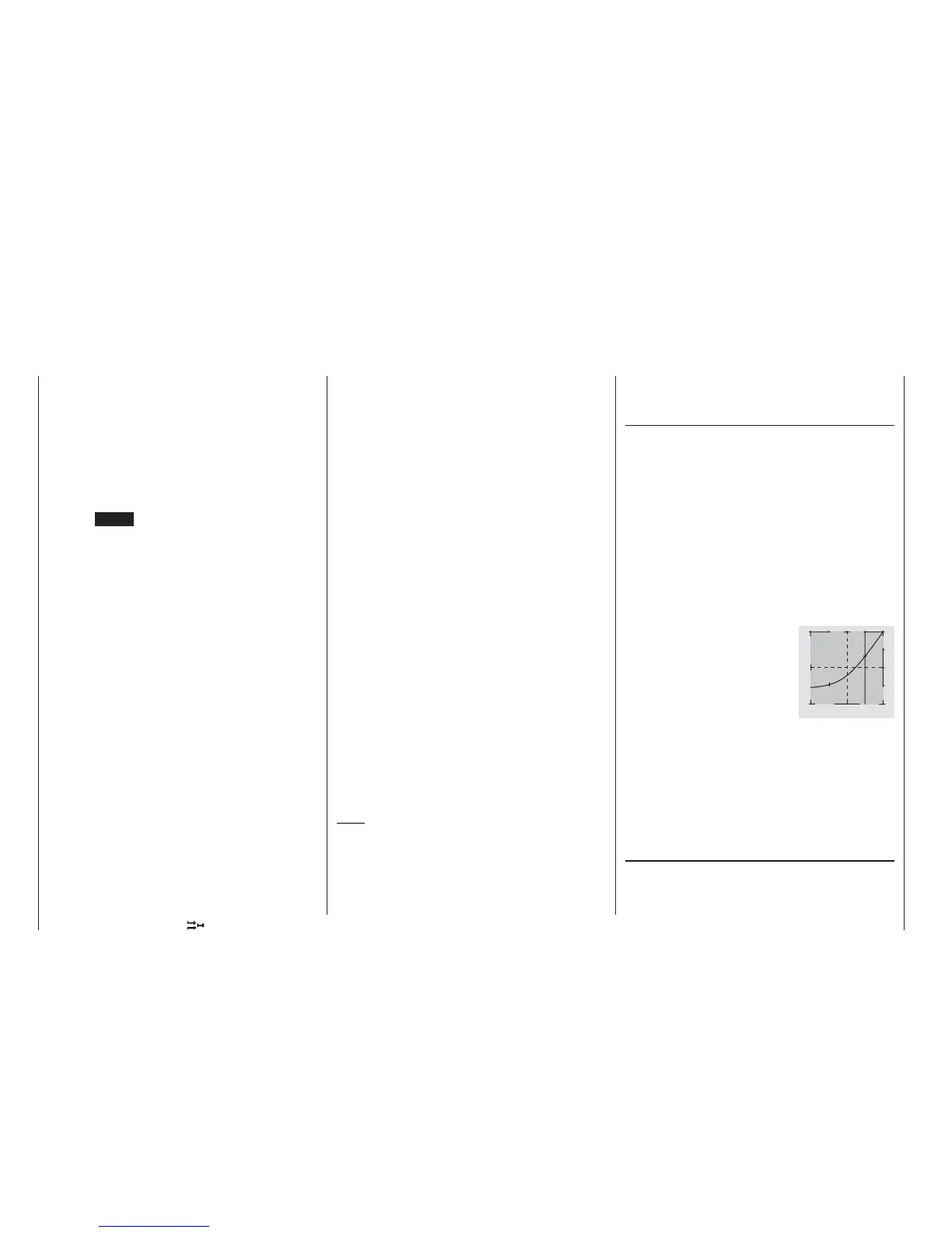
The diagram shows a three-point cur-
ve with a slightly altered throttle setting
below the reference point “1”. The cur-
ve has also been rounded off, as descri-
bed earlier.
kage needs to be rotated to the right through 45° by
the software, so that the pushrods from the swashpla-
te to the rotor head can be set exactly vertical, ensu-
ring that the blade control system works correctly, wi-
thout unwanted differential effects. This menu point
provides for this arrangement, eliminating the need
to make mechanical changes to the control linkages.
Negative angles equate to a virtual rotation of the ro-
tor head to the left; positive angles a virtual rotation to
the right.
Pressing CLEAR resets the input value to “0°”.
-
+
1 0 0
L H
1
OUTPUT
Stick travel