95
Program description: Mixers
less you have set a reduction in control travel. Ef-
fective gyro gain at full tail rotor defl ection can be
defi ned as follows:
“current slider position minus gyro
suppression value”,
i.e. at 0% gyro suppression the gyro gain remains
constant when a tail rotor command is given; at
50% suppression gyro gain is reduced to half if sli-
der 7 is moved to the +50% position (as shown
here); at >150% suppression, gain is reduced to
zero before full tail rotor defl ection in this slider po-
sition.
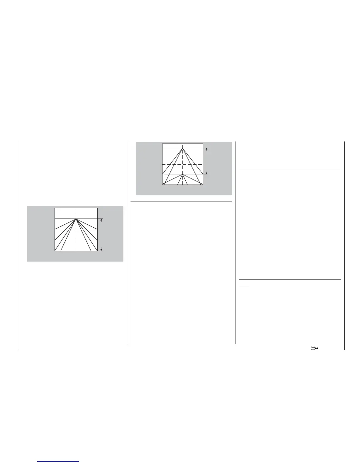
2. Linear gyro suppression with reduced control tra-
vel, e.g. -50% to +80% travel. Gyro gain can be va-
ried proportionally within these control limits. Here
again, for demonstration purposes the illustration
shows gyro gain varying according to tail rotor de-
fl ection for various values of the gyro suppression
parameter.
Adjusting the gyro sensor
To set up a gyro to achieve maximum possible stabi-
lisation of the helicopter around the vertical axis, ple-
ase note the following points:
• The control system must be as free-moving and
accurate (slop-free) as possible.
• There should be no “spring” or “give” in the tail ro-
tor linkage.
• You must use a powerful and – above all – fast
servo.
When the gyro sensor detects a deviation in yaw, the
faster it adjusts the thrust of the tail rotor, the further
the slider “7” (or other gyro gain adjustor) can be ad-
vanced, without the tail of the model starting to oscil-
late, and the better is the machine’s stability around
the vertical axis. If the corrective system is not fast
enough, there is a danger that the helicopter’s tail will
start to oscillate even at low gyro gain settings, and
you then have to reduce gyro gain further using slider
“7” to eliminate the oscillation.
If the model is fl ying forward at high speed, or ho-
vering in a powerful headwind, the net result of the
stabilising effect of the vertical fi n combined with the
gyro’s stabilising effect may also be an over-reaction
which manifests itself in tail oscillation. In order to ob-
tain optimum stabilisation from a gyro in all fl ight si-
tuations, gyro gain has to be adjusted from the trans-
mitter via slider “7” in conjunction with gyro suppres-
sion and / or the two adjustors on the NEJ-120 BB
gyro.
Additional notes on gyros with multi-stage variab-
le gyro gain (e.g. NEJ-120 BB)
Since you cannot pre-set gyro gain proportionally at
the transmitter using the slider, it makes sense to set
the lower level of gyro gain using adjustor 1 (e.g. for
aerobatics), and the higher level of gain using ad-
justor 2 (e.g. for hovering). In this case you can only
switch between these two set values, even if a pro-
portional slider control is used for function 7, i.e. pro-
portional adjustment is not available.
For this reason you should advance adjustor 2 to
the point where the model is on the brink of oscilla-
ting when hovering in calm conditions, and advan-
ce adjustor 1 to the point where the model’s tail does
not oscillate even when the helicopter is at maximum
speed and fl ying into a powerful headwind. Depen-
ding on the weather conditions and the type of fl ying
you wish to carry out, you can then switch gyro gain
to the appropriate setting from the transmitter, and – if
you wish – set gyro suppression to vary with tail rotor
control defl ection.
Swashplate rotation
Note:
If none of the types which can be selected in the
“Swashplate type” line of the »Helicopter type«
menu matches your model, then you can set up a uni-
que system in this menu.
With some rotor head control systems it is necessa-
ry to incline the swashplate in a direction which is not
the same as the intentional inclination of the rotor pla-
ne when a cyclic control command is given. For ex-
ample, if your model features the HEIM system and
is fi tted with a four-bladed main rotor, the control lin-
m i n
m a x
0 %
5 0 %
1 0 0 %
1 5 0 %
1 9 9 %
+ 5 0 %
- 1 0 0 %
Exemple:
+50%
Range of
transmitter
control 7
left centre right
Stick defl ection tail rotor
Gyro gain
m i n
m a x
1 3 0 %
1 9 9 %
5 0 %
1 9 9 %
+ 8 0 %
- 5 0 %
Exemple:
+80%
left centre right
Stick defl ection tail rotor
Gyro gain
Range of
transmitter
control 7