110
Program description: Mixers
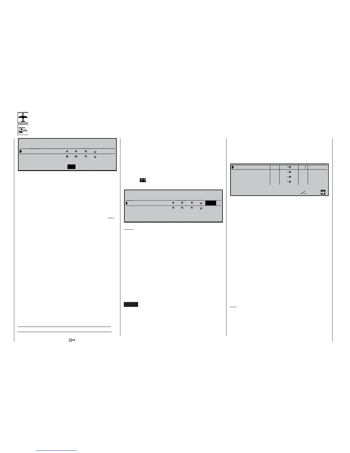
D U A L M I X E R
M i x e r 1 ? ? ? ? + 0 %
M i x e r 2 ? ? ? ? + 0 %
D i f f .
S E L
S E LS E L
t
In the default state of the mc-22s transmitter this
menu is initially suppressed. To activate it, move to
the »Suppress codes« menu (see page 49). Alterna-
tively, move to the »Basic settings« menu (see page
117) and select “yes” for the Expert mode; this must
be carried out before you set up a new model memo-
ry.
The two dual mixers are designed for coupling two
channels together to provide same-sens „
“ and
opposite-sense „
“ like a v-tail mixer, but with un-
restricted choice of channels, and optional differential
travel of the opposite-sense function.
In software terms this type of “dual mixer” is imple-
mented as standard, with the two aileron servos con-
nected to receiver outputs 2 and 5, and the two fl ap
servos to outputs 6 and 7. The fl aperons are cont-
rolled by the aileron stick and the transmitter cont-
rol which is assigned to input “6” in the »Control ad-
just« menu. Any further “NN 2” mixer which you
set up then operates the two ailerons as ailerons,
while an “NN 5” mixer operates them as fl aps. Si-
milarly, a free mixer “NN 6” operates both fl aps as
fl aps, while an “NN 7” mixer operates them as aile-
rons; see page 104.
The two freely programmable dual mixers in this
menu can also be used to couple together two more
receiver outputs in the same way; this would normal-
ly require more complex programming involving free
mixers.
At this point we will give an example of this type of
programming (see also the example on page 142):
Dual mixer
Same-sense / opposite-sense coupling of two channels
Large scale gliders often feature six wing control sur-
faces rather than four, all of which are required to
have superimposed aileron / fl ap functions. In our ex-
ample the two additional wing fl aps are connected to
receiver outputs 8 and 9.
Start by selecting mixer 1 or 2 with the rotary control
pressed in. After a brief press on the rotary control in
the left-hand SEL fi eld, enter output “8” in the inverse
video „
“ fi eld using the rotary control, and en-
ter output “9” using the middle SEL fi eld:
D U A L M I X E R
M i x e r 1 8 9 + 2 5 %
M i x e r 2 ? ? ? ? + 0 %
D i f f .
S E L
S E LS E L
t
Note:
The symbols „
“ and „
“ indicate the same /
opposed direction of travel of the control surface con-
nected to the servo in question – not the direction of
servo rotation! If the second control surface moves in
the wrong “sense” (direction), simply interchange the
two inputs, or use servo reverse in the »Servo adjust-
ment« menu; see page 56.
In the right-hand column defi ne the “degree of dif-
ferential”, as described in the »Wing mixers” menu
(see page 85). The effect of this function is to reduce
the travel of the down-going control surface compa-
red to the full travel of the control surface on the op-
posite wing. This process generates exactly the dual
coupling for servos 8 + 9 which is required. (Pressing
CLEAR erases the dual mixer, or resets the degree of
differential to 0%).
The two additional servos should now “follow” servos
2 + 5 as ailerons when an aileron command is given,
and should follow servos 6 + 7 as fl aps when a fl ap
command is given. To operate this combination cont-
rol system all you require is one more free mixer, lin-
king the aileron stick to the two servos 8 and 9. Move
to the »Free mixers« menu, locate a mixer which is
not yet in use, e.g. linear mixer 1, and set it up as fol-
lows:
L i n e a r M I X 1 A I 9 6 o f f = >
L i n e a r M I X 2 ? ? ? ? - - - -
L i n e a r M I X 3
? ? ? ? - - - -
L i n e a r M I X 4 ? ? ? ? - - - -
t y p e f r o m t o A d j u s t
S E L
t
S E L
S E L
An “AIL 8” mixer would move the two servos as
fl aps, i.e. in the same direction: „
“.
Now defi ne the mixer setting on the second display
page. If you wish, you can assign a switch to the mi-
xer, as shown in this example.
To be able to operate the two additional control sur-
faces as fl aps (as well as ailerons), assign the same
transmitter control to input 8 in the »Control adjust«
menu as input 6 (e.g. control 6), which – of course –
is already in use to control the existing fl aps connec-
ted to outputs 6 and 7. An alternative method of assig-
ning the transmitter control would be to defi ne a se-
cond linear mixer “6 8”, which has the same effect.
If you want the fl ap control system to be different in
each fl ight phase, you will need to program additio-
nal free mixers, which you can then activate for the
appropriate fl ight phase in the »MIX active/phase«
menu. However, the degree of differential can only be
set to one value, since the “Dual mixers” cannot be
programmed separately for different fl ight phases.
Tip:
You can check all the settings immediately in the
»Servo display« menu.