112
Fail-Safe settings
Fail-safe in the “PCM20” transmission mode
F A I L S A F E ( P C M 2 0 )
T i m e B a t t e r y F . S .
h o l d
o f f
S E L S E L
This menu appears in the multi-function list only if
you have selected the PCM20 transmission mode.
This mode of operation must be pre-set in the memo-
ry-specifi c »Base setup model« menu. The PCM20
transmission mode can be used with all receivers with
“mc” in the type designation (mc-12, mc-18, mc-20,
DS 20 mc receivers, etc.).
Fail-safe programming for SPCM20 mode will be dis-
cussed in the next section.
In this menu you can defi ne the behaviour of the re-
ceiver when a problem arises in the link between
transmitter and receiver, and you can also exploit the
option of moving one servo to a particular position
when the voltage of the receiver battery falls below a
certain value (“battery fail-safe”).
Fail-safe and interference
The operational security of Pulse Code Modulation
(PCM) is inherently higher than that of Pulse Position
Modulation (PPM), since the receiver incorporates an
integral micro-processor which detects whether a re-
ceived signal is valid, or is incorrect or garbled due to
outside interference. In the latter case the receiver au-
tomatically replaces the invalid signal with the last re-
ceived correct signal, which is stored in the receiver.
This time-limited “holding” procedure suppresses brief
interference caused by local drops in fi eld strength
and similar momentary problems, which otherwise re-
sult in the familiar “glitches”.
Caution:
If you use either of the PCM transmission modes
(PCM and SPCM), do make use of the enhanced
Program description: Special functions
safety features, by programming the throttle posi-
tion of glow-powered models to idle and the mo-
tor function of electric-powered models to Stop if
the Fail-Safe is triggered. It is then not so easy for
the pilot to lose all control of the model if interfe-
rence should occur; if this happens with the mo-
del on the ground, serious damage to property
and even personal injury can result.
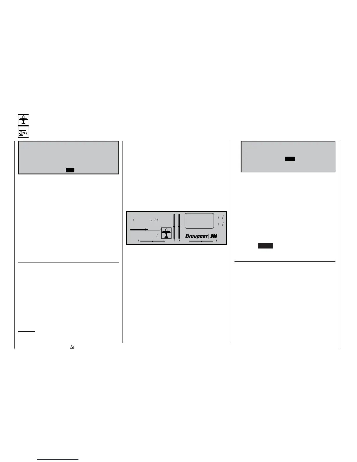
If you select the PCM 20 transmission mode but have
not yet carried out the fail-safe programming, you
will see a warning message on the screen when you
switch the transmitter on. The message remains on-
screen in the basic display for a few seconds:
Model name
#01 0:00h C73
H-J Sandbrunner
9.8V
4:10h
0 0 0 0
Stoppuhr
Flugzeit
0 00
0 00
:
S t o p p u h r
F l u g z e i t
:
If a longer period of interference affects the radio link
between transmitter and receiver, the PCM20 ope-
rating mode offers two optional types of fail-safe pro-
gramming, and you can select your preferred one
using the left-hand SEL fi eld.
1. “Hold” mode
If you confi rm the left-hand SEL fi eld with a brief
press on the rotary control, and then set “hold” in
the inverse fi eld, when interference strikes the ser-
vos will stay continuously at the position corres-
ponding to the last valid signal until the receiver
picks up another signal which it recognises as va-
lid.
2. Variable FAIL-SAFE programming with overwri-
te facility (display: “.25s, 0.5s or 1.0s”)
If you set a pre-selected time instead of “hold”
mode, the display initially changes as follows:
F A I L S A F E ( P C M 2 0 )
P o s i t i o n T i m e B a t t e r y F . S .
. 2 5 s o f f
S E L S E LS T O
With this arrangement “hold” mode is effective
when interference fi rst strikes, but after the set de-
lay has elapsed the servos move to previously de-
termined positions until the receiver again picks
up a valid control signal. As soon as the receiver
picks up valid control signals again, the “hold” pha-
se or the servos’ fail-safe position are abandoned
again immediately.
The delay time, i.e. the time from the onset of in-
terference to the triggering of the FAIL-SAFE
mode, can be set to any of three values: 0.25 sec.,
0.5 sec and 1.0 sec. These variations are desig-
ned to cater for models fl ying at different speeds.
Pressing CLEAR resets the fail-safe setting in the
inverse video fi eld to “hold”.
Setting the servo positions
The FAIL-SAFE servo positions are freely program-
mable for the receiver outputs 1 ... 8. Use the rota-
ry control to select the STO fi eld. Now move servos 1
... 8 to the appropriate positions using the transmitter
controls, then briefl y press the rotary control to store
those positions as the fail-safe settings. This data is
transmitted to the receiver at regular intervals, so that
the receiver can always revert to them if interference
should strike.
When you store the data – by giving the rotary control
a brief press – the following message appears on the
screen for a few moments:
Fail Safe
setup