115
Program description: Special functions
Teacher/pupil
Connecting two transmitters for Trainer (teacher / pupil, “buddy-box”) operations
4%!#(%2050),
0
4
#!)%,25
In the default state of the mc-22s transmitter this
menu is initially suppressed. To activate it, move to
the »Suppress codes« menu (see page 49). Alterna-
tively, move to the »Basic settings« menu (see page
117) and select “yes” for the Expert mode; this must
be carried out before you set up a new model memo-
ry.
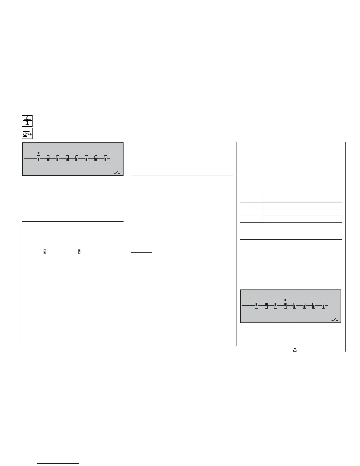
Setting up the Teacher transmitter
Up to eight control functions of the Teacher transmit-
ter “T” can be transferred to the Pupil transmitter “P”,
either individually or in any combination.
Select channel 1 to () using the rotary control, and
press the rotary control briefl y to switch between “T
(Teacher)” ( ) and “P (Pupil)” ( ) modes:
The model to be controlled by the pupil must be pro-
grammed completely in a model memory of the Tea-
cher transmitter, with all its functions including trims
and any mixer functions. The only functions of the Pu-
pil transmitter which are used when control is trans-
ferred from the Teacher transmitter are the signals
from the sticks and any other transmitter controls
which are fi tted.
The Teacher transmitter can be operated in PPM18,
PPM24, PCM20 or SPCM20 mode.
You must assign a Trainer transfer switch in order to
transfer control to the pupil; this is carried out on the
right of the screen. We advise the use of the momen-
tary switch, Order No. 4160.1, or the kick switch, Or-
der No. 4144, (converted to momentary switch func-
tion; see Appendix), as these types of switch allow
you regain control at the Teacher transmitter with the
least possible delay.
All the parts required are included in the opto-elec-
tronic Trainer system, Order No. 3289. Please refer to
the Appendix for details of installing these compon-
ents.
Setting up the Pupil transmitter
The Pupil transmitter must be fi tted with the Trainer
pupil module; this unit is connected to the transmitter
circuit board in place of the RF (Synthesizer) modu-
le, and transfers the control signals via the light-pipe
lead.
The following transmitters can be used as the Pupil
unit: GRAUPNER/JR D14, FM414, FM4014, FM6014,
mc-10, mc-12, mx-12, mc-14, mc-15, mc-16, mx-16s,
mc-16/20, mc-17, mc-18, mc-19, mc-20, mc-22, mc-
22s, mx-22 and mc-24, with four to eight control func-
tions.
The Pupil modules required for the transmitters stated above are
listed in the main GRAUPNER catalogue.
Important:
The Pupil transmitter must always be set to ope-
rate in PPM mode, regardless of the modulation
set on the Teacher transmitter, and …
… the control functions you wish to transfer must
act directly on the control channels, i.e. the recei-
ver outputs, without any type of mixer being invol-
ved.
If you are using an mc- or mx-series transmitter, it is
best to set up a free model memory with the appro-
priate model type (“Fixed wing” or “Heli”), and assign
it the model name “Pupil”. The stick mode (Mode 1
… 4) and “throttle min. forward / back” should be set
to suit the pupil’s preferences; all the other settings
should be left at their defaults. If the model type is
“Helicopter”, you should also check the throttle / col-
lective pitch function on the Pupil transmitter and re-
verse it if necessary, and set the idle trim correctly. All
other settings, mixers and coupling functions are car-
ried out exclusively in the Teacher transmitter, and are
transmitted from this unit.
With “D” and “FM” type transmitters you must also
check the direction of servo rotation and the stick
mode, and correct them if necessary by re-connec-
ting the cables inside the transmitter. Switch off all mi-
xers, or set them to “zero”.
When assigning the control functions the usual con-
ventions must be observed:
Channel Function
1 Throttle / Collective pitch
2 Aileron / Roll
3 Elevator / Pitch-axis
4 Rudder / Tail rotor
Trainer mode operations
Link the two transmitters using the light-pipe lead, Or-
der No. 3290.4 or alternatively the “ECO” Trainer lead,
Order No. 3290.5; see Appendix. The plug marked
“M” (Master) must be fi tted in the socket on the Tea-
cher transmitter, and the plug marked “S” (Student) in
the socket of the Pupil transmitter. Switch both trans-
mitters on.
Now select the functions 1 ... 8 which are to be trans-
ferred from the Teacher transmitter:
0
4)
4%!#(%2050),
#!)%,25