14
Operating notes
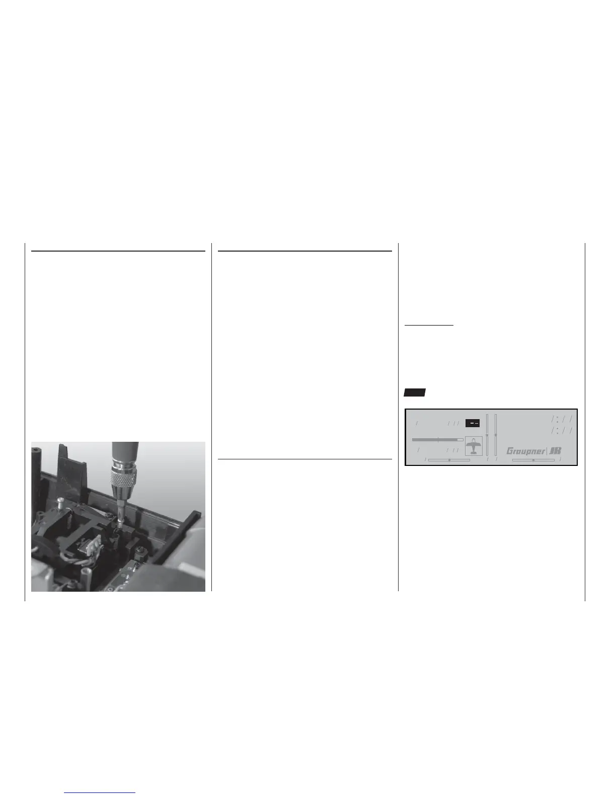
Stick centring force
The tension of the stick unit centring springs can be
adjusted to suit your personal preference: the ad-
justment system is located adjacent to the centring
spring. Rotate the adjustor screw with a cross-point
screwdriver to set your preferred spring force:
• Turn to the right (clockwise) = spring force harder;
• Turn to the left (anti-clockwise) = spring force sof-
ter.
Operating notes
Changing frequency bands and channels
The mc-22s transmitter is equipped as standard with
a PLL Synthesizer RF module. The channel you wish
to use is selected using the rotary control; plug-in
crystals are not required for the transmitter.
A detailed description of the procedure for using the
Synthesizer module and setting the appropriate chan-
nel is found in the section entitled “Using the transmit-
ter for the fi rst time – selecting channels” on page 22.
The set channel is displayed on the screen. A security
system prevents an RF signal being generated when
the transmitter is switched on. The RF module must
fi rst be activated in the software, which provides an
additional margin of safety.
Two sets / two transmitters are available for the 35 /
35B MHz band and the 40 / 41 MHz band:
Radio control sets:
Order No. 4737 35 / 35B MHz band
Order No. 4738 40 / 41* MHz band
Transmitters alone:
Order No. 4737.77 35 / 35B MHz band
Order No. 4738.77 40 / 41* MHz band
* Channels 281 and 282 in the 35 MHz band, and all channels in
the 41 MHz band, are not approved for use in Germany. Please
refer to the frequency table on page 168, The table also lists the
channels which may legally be used for the various model ty-
pes, i.e. model aircraft, model boats and model cars.
Please refer to the frequency table on page 168 for
a list of the channels which are valid in the European
continent at time of going to press.
The receiver must be operated on the same channel
and on the same frequency band as the transmitter.
You can use any GRAUPNER PLL Synthesizer re-
ceiver with the transmitter, together with all earlier
crystal-controlled GRAUPNER receivers, provided
that they are compatible with the transmission mo-
des PCM20, SPCM, PPM18 and PPM24 (see pages
7 and 8 and the main GRAUPNER FS catalogue for
more information on this subject).
If you wish to use earlier crystal-controlled GRAUP-
NER receivers, it is essential to use genuine GRAUP-
NER FMsss plug-in crystals exclusively (see page
168). The receiver crystal is marked “R” (Receiver),
and should be pushed fi rmly into the socket in the re-
ceiver.
Important note:
The RF-Synthesizer module is connected to the
transmitter circuit board by means of two cables. If the
cables are not plugged in correctly, or if the 4-pin plug
is withdrawn in order to install a Pupil module (see
page 163), the transmitter switches directly to the
basic display when switched on. Instead of a channel
number, the screen now displays the fl ashing symbol
“C––” ; in order to indicate that the RF module is not
ready for use:
-ODELNAME
H#
(*3ANDBRUNNER
6
H
3TWATCH
&LIGHTTM
Changing frequency bands:
For reasons of safety a switch of RF module from the
35 / 35B MHz to the 40 / 41 MHz band (or vice ver-
sa) can only be carried out by a GRAUPNER Service
centre.