147
Programming examples – Fixed-wing models
»Base setup model« (page 50)
B A S I C S E T T I N G S , M O D E L
M o d e l n a m e < >
S t i c k m o d e 2
M o d u l a t i o
n P P M 1 8
T r i m s t e p s 1 4 4 4
C H 1 A I L E E L E V R U D D
t
s
… for all four trim levers. You can check the effect of
the sensitivity you have selected in the »Servo dis-
play« menu.
You may fi nd it necessary to assign transmitter cont-
rols to particular inputs to operate the retractable un-
dercarriage and carburettor mixture adjustment. This
is carried out in the menu ...
»Control adjust« (page 58)
E n t e r 5 C n t r 5 0 % + 1 0 0 % + 1 0 0 % 0 . 0 0 . 0
E n t e r 6 C n t r 6 0 % + 1 0 0 % + 1 0 0 % 0 . 0 0 . 0
E n t e r 7 C n t r 7
0 % + 1 0 0 % + 1 0 0 % 0 . 0 0 . 0
E n t e r 8 2 0 % + 1 0 0 % + 1 0 0 % 0 . 0 0 . 0
o f f s e t - t r a v e l +
- t i m e +
S Y M A S Y
A S Y
S Y M
t
s
S E L
For example, you may like to use an external ON /
OFF switch connected to input 8 for the retracts, and
a proportional control, e.g. slider 7 on the centre con-
sole (connected to input 7) for mixture adjustment.
Note:
A time delay for the retracts may be a useful fea-
ture, providing a more realistic retraction / extension
speed, but this has no effect if you use the non-pro-
portional retract servo C713, Order No. 3887.
The retracts are extended and retracted when you
operate switch “2”. You may need to adjust the travel
of the transmitter control, and perhaps reverse that
channel by setting a negative value for the travel set-
ting.
F3A models fl y at extremely high speeds, and re-
spond very “solidly” to corrective movements of the
servos. However, in competition fl ying it is vital that all
abrupt control movements and corrections should be
kept to a minimum, as the judges will invariably notice
any lack of smoothness and dock a few points from
your score, so it is advisable to set exponential cont-
rol characteristics on the stick functions.
Switch to the menu ...
»Dual Rate / Exponential« (page 64)
A i l e r o n 1 0 0 % 0 %
E l e v a t o r 1 0 0 % +
3 0 %
R u d d e r 1 0 0 % + 3 0 %
D U A L E X P O
S E LS E L
t
s
Exponential values of around +30% on aileron, ele-
vator and rudder have proved to be a good star-
ting point, and you can set them in the right-hand co-
lumn of this menu using the rotary control. These va-
lues provide smooth, well-defi ned control of the typi-
cal F3A model.
(Many experts use higher values; even up to +60%
exponential.)
Since the response of (several) glowplug motors to
the throttle stick is by no means truly linear, you may
want to dip into the menu …
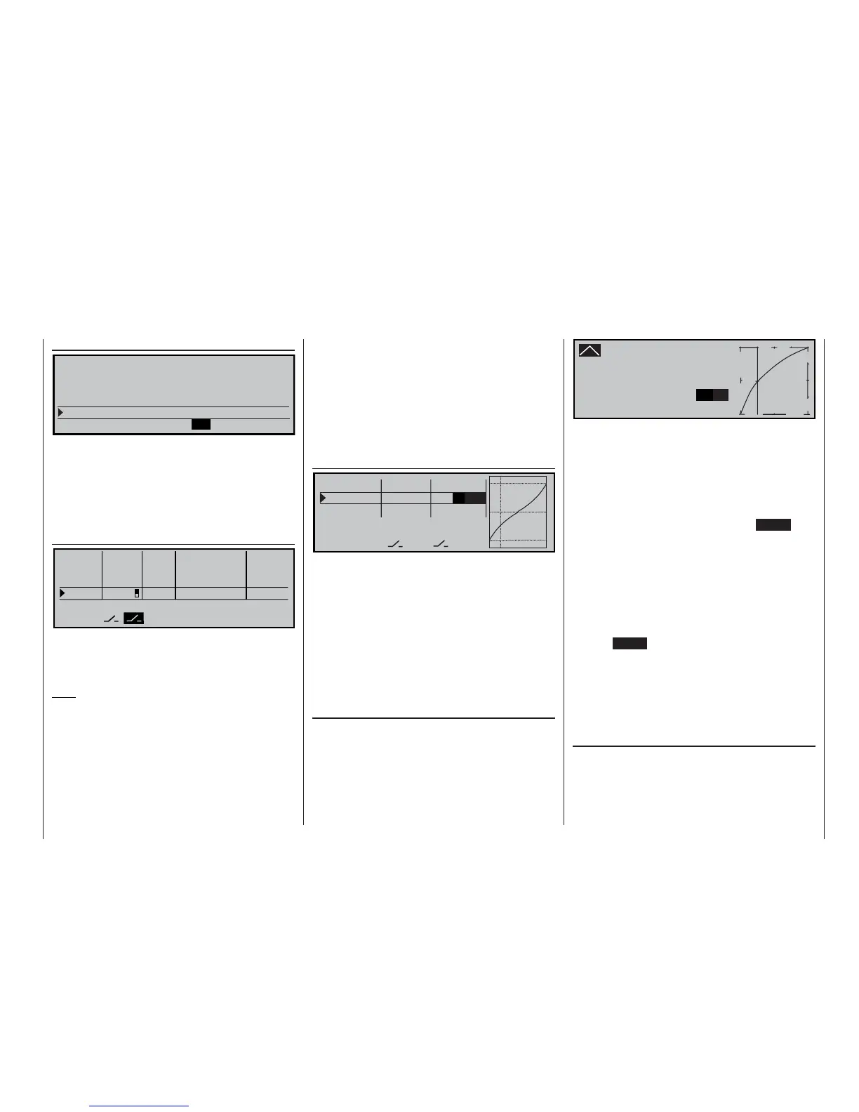
»Channel 1 curve« (page 68)
… to set what we might term a “bent”, i.e. non-linear,
throttle curve. In particular, four-stroke engines such
as the OS Max FS 120 call for a steep rise in the cur-
ve at the bottom end of the speed range. However,
you will need to experiment to fi nd the perfect throttle
curve. A typical Ch1 control curve for the motor might
look like this:
C h a n n e l 1 C U R V E
I n p u t - 5 0 %
C u r v e O u t p u t - 0 %
o n P o i n t 1
0 %
®
O U T P U T
-
+
1
1 0 0
Only three reference points, namely -100% cont-
rol travel (= “L, low”), +100% travel (= “H, high”) and
-50% control travel (“1”) produce the curve shown
here when rounded off.
This is the basic procedure:
1. Erase the reference point “1” which is present at
the centre point in the basic software setting: move
the Ch1 stick to centre and press the CLEAR but-
ton at the side.
2. Now move the Ch1 stick – and with it the vertical
line in the graph – to around -50% travel in the di-
rection of idle, and briefl y press the rotary control.
3. To obtain the curve shape shown here, use the ro-
tary control to raise this reference point to about
0% in the inverse video fi eld of the “Point” line.
4. Finally round off the curve by pressing the left-
hand ENTER button.
If you need to set additional reference points between
the left (“L”) and right (“H”) ends, repeat steps 2 and 3
using the same procedure.
If you operate the radio control system in PCM-20 or
SPCM-20 mode, it is advisable to store suitable fail-
safe settings using the menu ...
»Faile-safe adjust« (page 112 or 114)
… as “hold mode” is the default setting of the mc-22s
transmitter.
In its default form the transmitter prescribes “hold
mode” as the fail-safe setting; this equates to “do
nothing”, i.e. the receiver continuously passes the last
valid signals to the servos in the model: it “holds them