27
Transmitter control switch
It is often extremely desirable to switch a function on
or off automatically at a particular position of another
transmitter control, e.g. at a defi ned position of one of
the dual-axis sticks. Typical examples are switching a
stopwatch on and off to allow you to record the mo-
tor run time, lowering landing fl aps automatically, and
many others.
The program of the mc-22s includes a total of four
“switches” of this type. These software switches are
termed “G1 … G4”, and to use one all you have to do
is defi ne the trigger point along the travel of the trans-
mitter control; this is done simply by pressing a but-
ton. There are also “inverted switches”, which have
the same function but the reversed direction of effect.
They are therefore termed “G1i … G4i”.
Of course, control switches can also be combined
in any way with the external switches described pre-
viously; in this way many more complex problems can
be solved.
This manual includes a range of instructive examples
which make programming as simple as child’s play.
Please refer to the programming examples in the sec-
tion starting on page 72, 102 and 132.
Fixed switches: FXI and FX
This type of switch switches a function – such as a ti-
mer – on permanently (closed fi xed switch) or off per-
manently (open fi xed switch); alternatively it supplies
a fi xed input signal to a control function, e.g. FXI =
+100% and FX = -100%. For example, a fi xed switch
can be used in fl ight phase programming to switch a
servo or a speed controller between two settings. You
will fi nd another example on page 107.
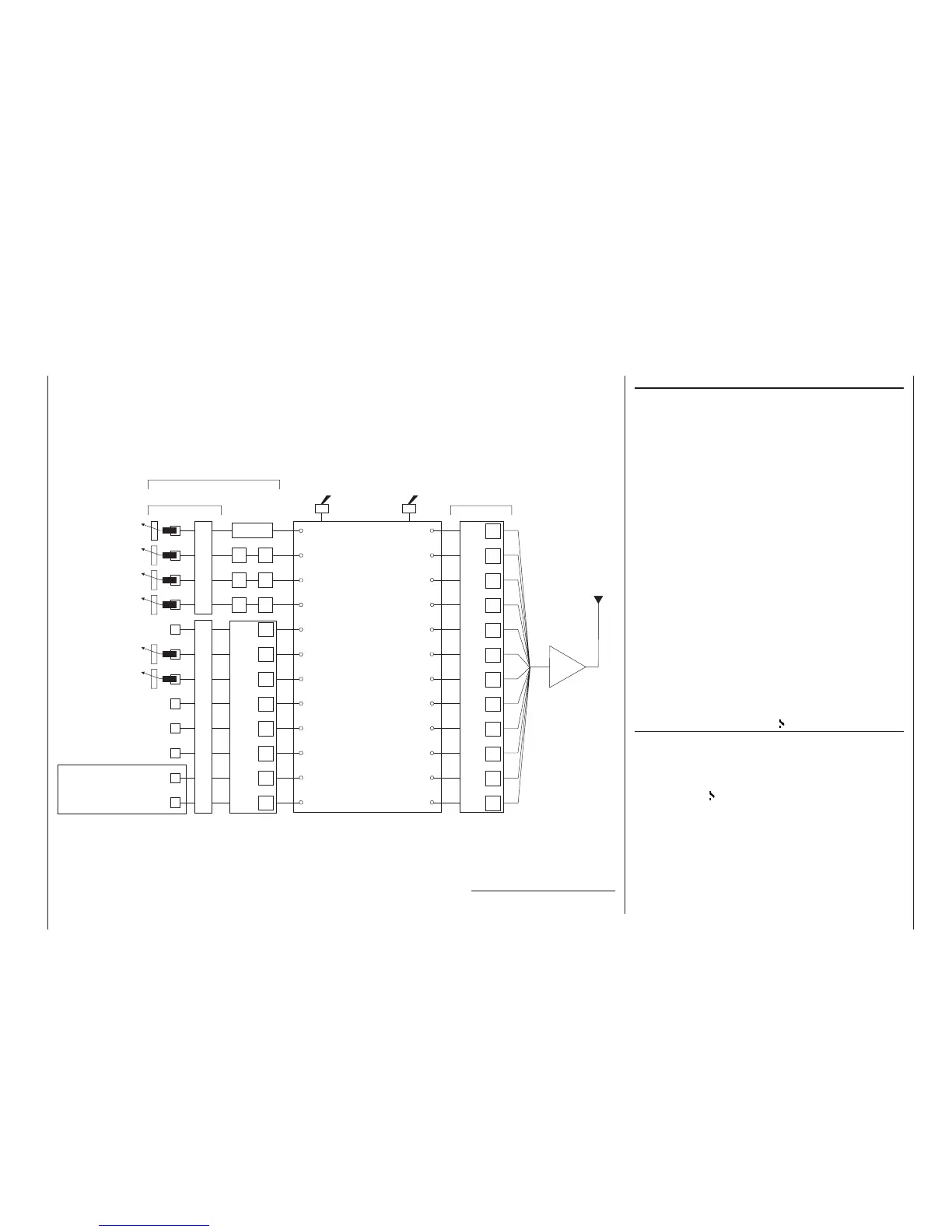
Defi nition of terms
Control function
Control channel
Aerial
RF
»Servo adjustment«: reverse - centre - travel - limit
mc
-22s programs
For example:
Model type
Helicopter type
Control switch
Auxiliary switch
Phase setting
Phase assignment
Undelayed channel
Wing mixers
Helicopter mixer
Free mixers
MIX active/phase
MIX-only channel
Dual mixer
Two-position switch
or three-position
switch
For switching mixers, auto-
rotation, fl ight phases, …
Function input
Channel 1
curve
DR
DR
DR
EXPO
EXPO
EXPO
Dual-axis stick unit
Dual-axis stick unit
e.g. Optional *
transmitter control 5
Transmitter controls 6
(slider)
Transmitter controls 7
(slider)
e.g. Optional *
transmitter control 8
e.g. Optional *
transmitter control 9
e.g. Optional *
transmitter control 10
Unrestricted assignment
by software
Control assignment 1 … 4Unrestricted transmitter control assignment, inputs 5 … 12
»Control adjust«: offset - travel - time
Transmitter control
Some of the transmitter cont-
rol inputs 5 … 12 are pre-as-
signed in the basic software
programming.
Transmitter control inputs 1 …
4 can be interchanged in the
»Base setup model« menu.
The above transmitter cont-
rols can be assigned to inputs
5 … 12 in any order.
Mixer input
Mixer output
* Optional transmitter controls:
see Appendix, pages 164 - 166
1
2
3
4
5
6
7
8
9
10
11
12
5
6
7
8
9
10
11
12