37
Model helicopters
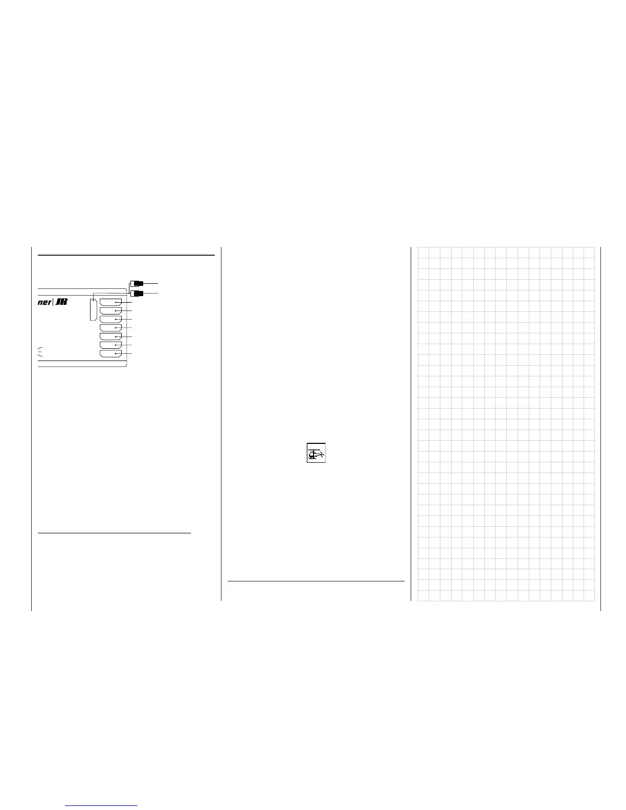
Receiver socket sequence
The servos must be connected to the receiver output
sockets in the following sequence:
Outputs not required are simply left unused.
For more details on the different types of swashplate
please refer to the »Helicopter type« menu descri-
bed on page 53.
If you are fl ying a model helicopter fi tted with a PPM-
FM receiver made by another manufacturer*, which
was previously fl own using another make of transmit-
ter, e.g. with the mc-22s for Trainer mode operations,
it may be necessary to re-arrange the receiver ser-
vo outputs. However, an alternative method is to use
the “Receiver output” sub-menu of the »Base setup
model« menu; see page 51. Different methods of in-
stalling servos and control linkages may make it ne-
cessary to reverse the direction of rotation of some
servos when programming. In both cases this is car-
ried out in the »Servo settings« menu; see page 56.
Notes for modellers upgrading from the mc-20:
• Compared with the mc-20, the collective pitch and
throttle servo sockets are interchanged at the re-
ceiver; see the table in the left-hand column.
• A standard feature of the mc-20 is a slider for col-
lective pitch trim, connected to the CH6 socket on
the transmitter circuit board. If you want to retain
the slider for collective pitch trim on the mc-22s you
7
6
5
4
3
2
1
8/Batt.
izer-MICRO-SUPERHET
1 6
FM
Best.-Nr.
7052
s 35MHz/35MHz-B-Band
Made in Malaysia
S C A N
! #
Receiver battery
Y-lead, Order No. 3936.11 or 3936.32
(Speed governor)
(Gyro gain)
Throttle servo (speed controller: electric motor)
Unused or pitch-axis servo 2
Tail rotor servo (gyro system)
Pitch-axis servo 1
Roll servo 1
Collective pitch or roll servo 2 or pitch-axis
servo 2
will need to set up a suitable mixer in the »Free mi-
xers« menu, e.g. a mixer 8 1, program a sym-
metrical mixer input of around 30%, and assign
transmitter control 6 or 7 to mixer input “8” in the
»Control adjust« menu – depending on the input
to which the slider is connected. This assumes that
the slider is not already in use for another purpose.
However, we also recommend that you de-coup-
le transmitter control 6 or 7 from input 6 or 7 in the
»MIX-only channel« menu, so that control 6 or 7
cannot also operate the associated servo. See ex-
ample 3 on page 107.
Different methods of installing servos and control lin-
kages may make it necessary to reverse the direction
of rotation of some servos when programming. You
can correct such problems by using the servo reverse
facility located in the »Servo adjustment« menu on
page 56.
All Codes (menus) which are relevant to model heli-
copters are marked with a “helicopter” symbol in the
“Program descriptions”:
This means that you can easily skip irrelevant menus
when programming a model helicopter.
* GRAUPNER does not guarantee that GRAUPNER radio cont-
rol systems will work correctly in conjunction with receiving sys-
tems and radio control equipment made by other manufacturers.