59
(The switch number refers to that shown in the
»Switch display« menu; see page 72).
As mentioned on page 27, the transmitter control
itself can also be used as a switch, i.e. the input
can be toggled to and fro between the two end-
points at a position of the transmitter control which
you can defi ne in the »Control switch« menu.
Instead of moving a switch to the “ON position”,
press ENTER to move on to the “expanded swit-
ches”:
Use the rotary control to select the control switch
G1 ... G4 or one of the software “inverted” control
switches G1i ... G4i, and confi rm your choice with
a brief press on the rotary control.
The two fi xed switches pass a constant signal to
the input:
FXI = +100%, FX = -100%
(Other values can be selected by altering the de-
fault setting in the “Travel” column.)
To erase a switch, press the CLEAR button when
you see the message:
“Move desired switch in ON position”.
For further information on control switches please
refer to the »Control switches« menu on page
72. If you have assigned a control switch, it is es-
sential to assign a transmitter control to it in that
menu!
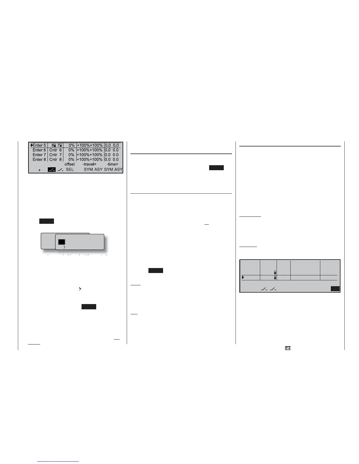
Column 3 “Offset”
The centre point of each transmitter control, i.e. its
zero point, can be changed in this column; the adjust-
ment range is -125% to +125%. Pressing CLEAR re-
sets the offset value to 0%. See pages 81 and 135 for
typical applications of this feature in conjunction with
fl ight phase programming.
Column 4 “–Travel+”
In this column you can set the travel of the transmit-
ter control to any value within the range -125% to
+125%. At the same time you can use the software to
reverse the direction of effect of the transmitter con-
trol. In contrast to altering servo travel, changing the
transmitter control travel setting affects all mixer and
coupling inputs, i.e. all servos which are infl uenced by
that transmitter control.
Transmitter control travel can be adjusted symmetri-
cally (SYM) to both sides, or asymmetrically (ASY). In
the latter case you must move the stick in the appro-
priate direction before altering the setting. When the
fi eld changes to inverse video (black background) you
can change the setting using the rotary control.
Pressing CLEAR resets the transmitter control travel
to 100%.
Note:
For technical reasons the control travel of the two sli-
ders in the centre console may be limited to less than
+/-100%. If necessary, you can compensate for this
by increasing the control travel.
Tip:
You can call up the »Servo display« menu to check
the new settings directly.
Column 5 “Time”
A delay within the range 0 to 9.9 sec. can be pro-
grammed for all function inputs 5 ... 12, either symme-
trically or asymmetrically. Use the rotary control to se-
lect SYM or ASY in the right-hand column, then press
the rotary control.
If you opt for an asymmetrical delay setting, you must
move the transmitter control in question to the appro-
priate end-point (or move the switch in the correspon-
ding direction), so that the inverse video fi eld changes
from one side to the other. You can then set the de-
lay separately for each side of neutral using the rota-
ry control.
Application:
Retractable undercarriage with wheel doors (cont-
rolled by two servos):
• Extend: doors fast, wheels slow;
• Retract: wheels fast, doors slow.
Example:
Wheel doors: Servo 11
Wheels: Ser vo 12
%NTER#NTR
%NTER#NTR
%NTER
%NTER
OFFSETTRAVELTIME
!39
39-
!39
39-3%,
L
You can also adjust the travel characteristics of ser-
vos 11 and 12 using the “Offset” and “Travel” points
in the transmitter control menu. Use the »Servo dis-
play« menu to check the results of your actions.
Program description: Transmitter controls
M o v e d e s i r e d s w i t c h
o r c o n t r o l
( e x t . s w i t c h : E N T E R )
C n t r l / f i x e d s w i t c h
G 1
G 2 G 3 G 4 F X I
F X
G 1 i G 2 i G 3 i G 4 i