70
Program description: Transmitter controls
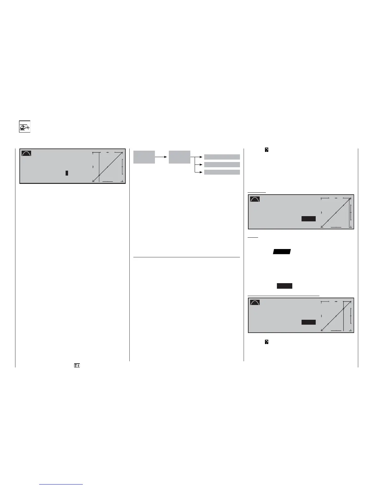
Channel 1 curve
Control characteristic for throttle / collective pitch curve
C h a n n e l 1 C U R V E
I n p u t - 6 0 %
C u r v e O u t p u t - 6 0 %
o f f P o i n t
?
®
O U T P U T
-
+
1
1 0 0
In the default state of the mc-22s transmitter this
menu is initially suppressed. To activate it, move to
the »Suppress codes« menu (see page 49). Alterna-
tively, move to the »Basic settings« menu (see page
117) and select “yes” for the Expert mode; this must
be carried out before you set up a new model memo-
ry.
In most cases the throttle response or the collective
pitch response is not linear, and in this menu you can
set up a curve to compensate for the non-linearity.
The menu enables you to change the control charac-
teristic of the throttle / collective pitch stick, i.e. the
curve you program here affects the throttle servo and
the collective pitch servos equally.
In contrast to the «Channel 1 curve« menu for fi xed-
wing models, in the Heli menu system the curve can
be adjusted separately for each fl ight phase in a given
model memory, provided that you have already speci-
fi ed fl ight phases in the »Auxiliary switch«, »Phase
setting« and »Phase assignment« menus (pages
75, 79, 80). The name of each fl ight phase is display-
ed on the screen (see above); in this case “Hover”.
The control curve can be defi ned by up to fi ve points,
termed “reference points” in the following section,
which can be positioned at any point along the stick
travel.
In this case please note that the curve set at this
point acts as input signal for the mixers in the »Heli-
copter mixer« menu, page 90:
In the basic software set-up, three reference points
defi ne a linear “curve” as the base setting, namely the
two end-points at the bottom end of the stick travel “L”
(low = -100% travel) and the top end of the stick tra-
vel “H” (high = +100% travel), together with point “1”,
which is exactly in the centre of the stick travel.
We recommend that you leave both end-points of the
“Channel 1 curve” at +/-100%, otherwise you may not
be able to exploit the full extent of the curve in the
subsequent curve mixers located in the »Helicopter
mixer« menu.
If you have not already done so, switch to the approp-
riate fl ight phase.
Setting and erasing reference points
You will fi nd a vertical line in the graph, and you can
shift this between the two end-points “L” and “H” by
moving the relevant transmitter control (throttle / col-
lective pitch stick). The current stick position is also
displayed in numeric form in the “Input” line.
The point at which this line crosses the curve is ter-
med the “Output”, and can be varied at the reference
points within the range -125% to +125%. This cont-
rol signal affects the throttle and collective pitch ser-
vos, and all subsequent mixer and coupling functions.
In the example above, the stick is at -60% control tra-
vel and also generates an output signal of -60%, sin-
ce the curve is linear.
Between the two end-points “L” and “H” you can now
insert a maximum of three reference points. The mini-
mum spacing between two adjacent reference points
is around 30% travel of the transmitter control.
If you now move the stick, the inverse video questi-
on mark immediately appears, and you can place
a reference point at the corresponding stick positi-
on by pressing the rotary control. Up to two further
points can be placed between the extreme points “L”
and “H”; the order in which you place them is not sig-
nifi cant, as the reference points are automatically re-
numbered sequentially from left to right in any case.
Example:
C h a n n e l 1 C U R V E
I n p u t + 9 0 %
C u r v e O u t p u t + 9 0 %
o f f P o i n t H
+ 1 0 0 %
®
O U T P U T
-
+
2
1 0 0
1
3
« H o v e r »
Note:
In this example the stick is located in the immediate
vicinity of the right reference point “H”. That is why the
“point” value “+100%” is in inverse video (black back-
ground).
If you wish to erase one of the set reference points
1 to 3, move the stick close to the reference point in
question. The reference point number and the asso-
ciated reference point value now appear in the “Point”
line. Press the CLEAR button to erase that point.
Example - erasing reference point 3:
C h a n n e l 1 C U R V E
I n p u t + 5 4 %
C u r v e O u t p u t + 5 4 %
o f f P o i n t 3
+ 5 4 %
®
O U T P U T
-
+
2
1 0 0
1
3
« H o v e r »
When the point has been erased, the inverse questi-
on mark re-appears after “Point”.
Collective
pitch stick
Channel 1
curve
Collective pitch
Ch1 throttle
Ch1 tail rotor
Menu »Helicopter mixer«