72
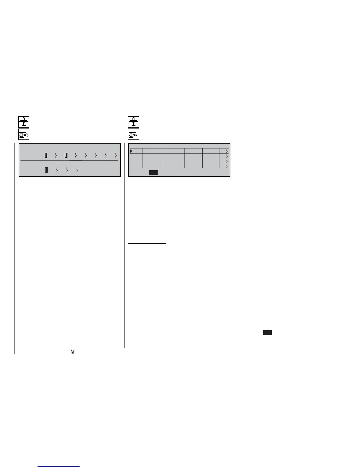
Switch display
Switch settings
Control switch
Assigning control switches
S w i t c h 1 2 3 4 5 6 7 8
C o n t r l G 1 G 2 G 3 G 4
S w i t c h
This display enables you to check the various func-
tions, and provides an overview of the external swit-
ches installed in your transmitter, together with the
programmable control switches.
When you operate an external switch, the number
of that switch becomes obvious on-screen becau-
se its normal OFF symbol changes to an ON symbol,
and vice versa. Closed (ON) switches are always dis-
played in inverse video, i.e. on a dark background, to
make them more readily noticeable.
The same applies to the control switches G1 ... G4:
when you operate the associated transmitter control
(i.e. the one assigned in the »Control switch« menu)
you can immediately see the number of the control
switch and the direction of switching.
Note:
The numbering 1 to 8 of the external switches shown
here equates to the numbers 0 to 7 on the transmitter
circuit board. However, the switch numbers are of no
importance for programming.
Program description: Switches
C O N T R O L S W I T C H
G 1 f r e e 0 % = > G 1
G 2 f r e e 0 % = > G 2
G 3 f r e e 0 %
= > G 3
G 4 f r e e 0 % = > G 4
S E L
t
In the default state of the mc-22s transmitter this
menu is initially suppressed. To activate it, move to
the »Suppress codes« menu (see page 49). Alterna-
tively, move to the »Basic settings« menu (see page
117) and select “yes” for the Expert mode; this must
be carried out before you set up a new model memo-
ry.
Many auxiliary functions are best controlled automati-
cally by a particular (freely programmable) position of
a transmitter control or stick, rather than by a conven-
tional switch.
Typical applications:
• Switching an on-board glowplug energiser on
and off, according to the throttle position or motor
speed. In this case the switch for the plug energi-
ser is controlled by a mixer at the transmitter.
• Switching a stopwatch on and off, to time the mo-
tor run of an electric motor.
• Switching a “combi-switch” mixer (coupled aileron
/ rudder) on and off automatically when airbrakes
are extended, for example, to allow you to match
the model’s angle of bank to the slope of the
ground when landing on a ridge, as the mixed rud-
der would affect the model’s heading at this time.
• Changing various settings on the landing ap-
proach when the throttle stick is reduced below a
pre-set switching point; the settings could be: ex-
tending landing fl aps, altering the elevator trim,
and / or triggering specifi c Dual Rate, Exponenti-
al and Differential settings. An external switch can
also be assigned separately in column 5, to overri-
de the control switch.
The mc-22s program features four of these control
switches, designated G1 to G4, and they can be in-
cluded without restriction in the free programming of
the external switches, i.e. they can be assigned to a
function and reversed (inverted) if necessary.
This means that you have the opportunity to assign
switches at all points in the program where their use
makes sense. At these points you can select one of
up to eight external switches, one of the control swit-
ches G1 ... G4, or alternatively one of the inverted
control switches G1i ... G4i, all of them presented in
a list.
The inverted control switches can be used in combi-
nation with a separate external switch (see below) to
generate more complex switch combinations.
The basic procedure:
1. Initially only the SEL function fi eld features at the
left of the bottom line.
2. Hold the rotary control pressed in, and select the
control switch 1 to 4 you wish to use.
3. Press the rotary control briefl y.
4. Use the rotary control to select the associated
transmitter control.
5. Press the rotary control to end the select procedu-
re.
6. You will now see additional fi elds (STO, SEL,
switch symbol) which you can select by turning
the rotary control.
7. Press the rotary control.
8. Select the setting using the rotary control.
9. Press the rotary control to end the input procedu-
re.
10. Press the ESC button to leave the menu.