78
Program description: Flight phases
Phase setting
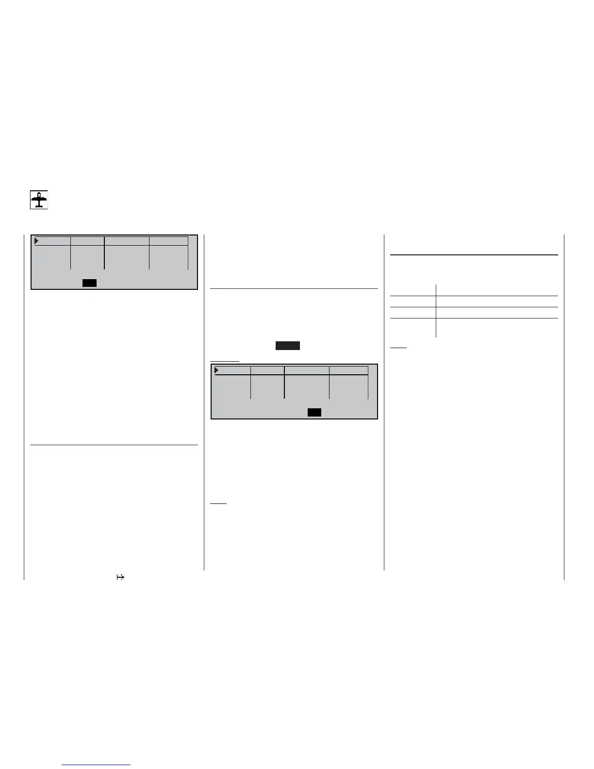
Setting up fl ight phases
P h a s e 1
0 . 0 s
P h a s e 2 0 . 0 s -
P h a s e 3 0 . 0 s -
P h a s e 4
0 . 0 s -
N a m e S w i t c h t i m e s t a t u s
S E L
S E L
V
t
In the default state of the mc-22s transmitter this
menu is initially suppressed. To activate it, move to
the »Suppress codes« menu (see page 49), or set
this menu point to “yes” in the »Basic settings«
menu (see page 117) before you set up a new model
memory.
The mc-22s enables you to program up to four groups
of settings within any one model memory; the settings
typically differ from each other in order to cater for dif-
ferent stages of a fl ight; these grouped settings are
generally termed fl ight phases.
When setting up fl ight phases for fi xed-wing models
you start at this menu point, where individual phases
are assigned names, and a transition time can be set
to provide a smooth transition from one phase into
the next.
“Name” column
Press the rotary control and select the most suitable
phase name for Phases 1 to 4 from the on-screen list.
The phase name will be included in all phase-specifi c
menus (see list on page 76) and is also shown in the
basic display. Note that you do not necessarily have
to start with Phase 1 and continue in turn.
However, “Phase 1” is always the “normal phase”, i.e.
this phase is always active if:
• no phase switch has been programmed in the
»Phase assignment« menu, and
• no phase has been assigned to particular switch
combinations.
The phase name «Normal» would therefore be a sen-
sible choice for “Phase 1”. The names themselves
have absolutely no technical signifi cance in terms of
programming; their only purpose is to help you iden-
tify them in the course of further programming, and
know which fl ight phase is switched on at any one
time.
“Switch time” column
When you switch between fl ight phases, it is advisab-
le to program a “soft” transition into (!) the next phase;
this is carried out by entering a transition time in this
column; the range available is 0 to 9.9 sec. The mc-
22s also allows you to set different transition times
for switching from, say, Phase 1 to Phase 3, and from
Phase 3 to Phase 1 (CLEAR = 0.0 sec).
Example:
P h a s e 1 N o r m a l
4 . 0 s +
P h a s e 2 L a u n c h 2 . 0 s
P h a s e 3 L a n d i n g 5 . 0 s +
P h a s e 4
0 . 0 s
-
N a m e S w i t c h t i m e s t a t u s
S E L S E L
V
t
In this example the set transition time from any other
phase into Phase 1 “normal” is 4.0 seconds, but if you
switch from, say, Phase 1 to Phase 3 the transition
time is 5.0 seconds.
Unequal transition times as shown in our example
can be useful when switching between fl ight phases
which differ widely, such as between aerobatics and
normal fl ight.
Note:
The “switch time” set here also applies to the »Wing
mixers« menu; see page 84, to avoid abrupt changes
between phase-specifi c mixers.
The next stage is to select the »Phase assignment«
menu (see page 80) and defi ne the “phase switches”
you wish to use. Once these are set, you can get
started on programming the settings for the individual
fl ight phases in the phase-specifi c menus.
“Status” column
The phases 1 ... 4 which have already been assigned
to a switch are shown in the right-hand column of the
screen display:
Symbol Symbol
– No switch assigned
+ Phase can be called up by switch
Indicates the currently active phase
number
Note:
A useful aid when programming different fl ight pha-
ses is the “Copy fl ight phase” option which you will
fi nd in the »Copy / Erase« menu. The fi rst step is to
establish the parameters for a particular fl ight phase;
you then copy these settings into the next fl ight phase
where they can be modifi ed to meet the requirements
of the new stage of fl ight.