84
What is a mixer?
The basic function
Wing mixers
Program description: Mixers
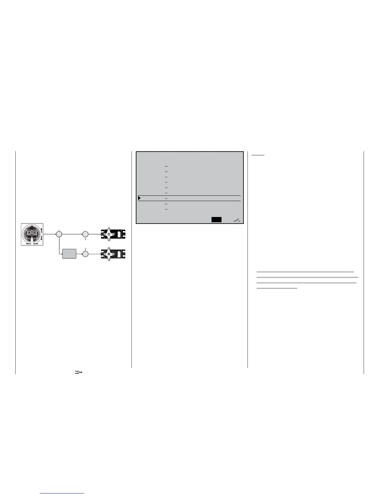
In many models it is often desirable to use a mixer to
couple various control systems, e.g. to link the aile-
rons and rudder, or to inter-connect two servos where
two control surfaces are actuated by separate servos.
In all these cases the signal at the “output” of the con-
trol function at the transmitter stick – i.e. at the control
function input (see sketch) – is “bled off”, and the de-
rived signal is then allowed to affect the “input” of ano-
ther control channel in a defi ned manner, so that it af-
fects a particular receiver output.
Example: controlling two elevator servos from the
elevator stick
The software of the mc-22s transmitter contains a lar-
ge number of pre-programmed coupling functions as
standard, which are designed to mix together two (or
more) control channels. The mixer required in this ex-
ample is supplied “ready-made”, and just has to be
activated in the software by accessing the »Model
type« menu.
The software also includes four freely programmable
linear mixers, two curve mixers and two dual mixers
(see below) in each of the fi xed-wing and helicop-
ter programs, all of which can be used in each model
memory.
For more information, please refer to the general no-
tes on »Free mixers« in this manual, in the section
starting on page 102.
3 3
8
Servo
4,8 V
C 577
Best.-Nr. 4101
Servo
4,8 V
C 577
Best.-Nr. 4 101
Transmitter
control
Control function
input
Control channel
(receiver output)
Mixer
menus
Mixer
Servo 1
Servo 2
(Display varies according to model type selected in the »Model
type« menu)
The mc-22s program contains a series of pre-pro-
grammed coupling functions, and all you have to do is
set the mixer ratios and (optionally) assign a switch to
the selected mixer.
The number of pre-programmed mixer functions in
the mixer list will vary according to the “model type”
you have already selected (tail type and number of
wing servos – see page 52). Moreover, all mixer func-
tions can be programmed separately for any different
fl ight phases you have set.
If you have set up multiple fl ight phases in the »Pha-
se setting” and »Phase assignment« menus, the
name of the current fl ight phase will be displayed at
the bottom of the screen, e.g. «Normal».
The screen shot above lists the (maximum) possib-
le mixer functions. For example, if your model is not
equipped with camber-changing fl ap servos, and you
have not entered any fl ap servos in the »Model type«
menu, all the fl ap mixers are automatically excluded
from the program. This makes the menu clearer and
easier to understand, and also helps to avoid pro-
gramming errors.
Notes:
• The transmitter control for the airbrake mixers can
be re-programmed in the »Model type« menu from
channel 1 to channel 8 or 9.
• The position of the camber-changing fl aps in the
individual fl ight phases is defi ned primarily by the
Offset value you have set in the »Control ad-
just« menu; see right column on page 135. Ho-
wever, if you wish to be able to vary the fl ap set-
tings in fl ight, or generally prefer manual fl ap con-
trol, any transmitter control assigned to “input 6”
can be used; see »Control adjust«, page 58. For
example, this might be one of the two sliders fi tted
as standard. This control operates the two fl ap ser-
vos connected to receiver output 6, or outputs 6
and 7, assuming that you have entered “... 1/2 FL”
in the “Ailerons / fl aps” line of the »Model type«
menu. However, we recommend that you reduce
the transmitter control travel to 25% or even less,
as this ensures that you have fi ne control of the
fl aps using the slider.
• Any transmitter control assigned to input 7 is de-
coupled by the software if your model has two fl ap
servos; this is intended to avoid malfunctions and
programming errors.
• The fl ap function of the ailerons can be adjusted
either in the »Control adjust« menu (see page
58), by programming input 5 in a similar way to in-
put 6, or alternatively by programming the wing mi-
xer Flap 6 5 aileron.
• If you wish to set up a “Butterfl y” (Crow) braking
system, i.e. raised ailerons and lowered fl aps, this
is carried out independently of the procedures
mentioned above; instead appropriate values are
set in the wing mixers Brake 5 Aileron and (if re-
quired) Brake 6 fl ap.
• If your model features a multi-fl ap wing and a
“Crow” or “Butterfl y” braking system (see below),
but without separate airbrakes, input 1 is not re-
A i l e r o n d i f f e r e n c e + 0 %
F l a p d i f f e r e n c e + 0 %
A i l e r o n s 2 > 4 R u d d e r + 0 %
A i l e r o n s 2 > 7 F l a p s +
0 %
B r a k e > 3 E l e v a t o r + 0 %
B r a k e > 6 F l a p s + 0 %
B r a k e > 5 A i l e r o n s + 0 %
E l e v a t o r 3 > 6 F l a
p s + 0 % + 0 %
E l e v a t o r 3 > 5 A i l e r o n + 0 % + 0 %
F l a p s 6 > 3 E l e v a t o r + 0 % + 0 %
F l a p s
6 > 5 A i l e r o n s + 0 % + 0 %
R e d u c t i o n o f d i f f . + 0 %
S Y M A S Y
t
s