87
Program description: Mixers
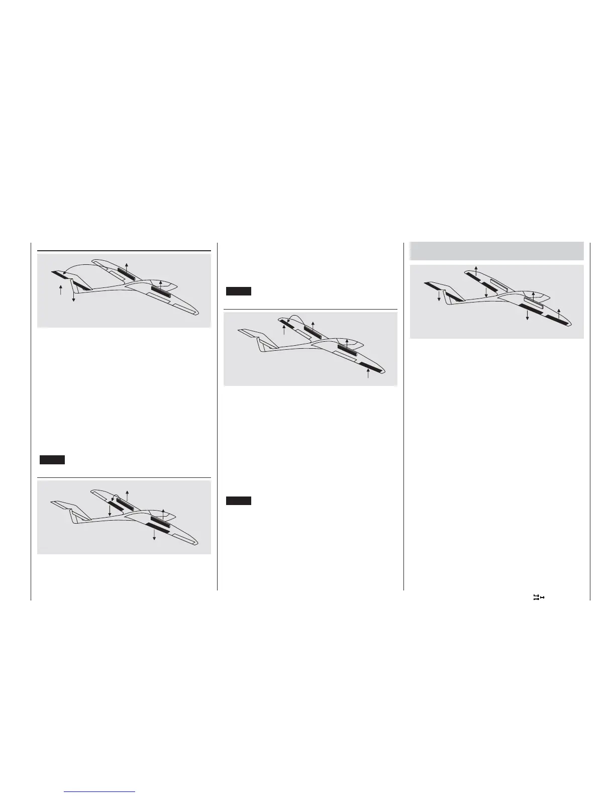
Brake 3 elevator
When any form of airbrakes is extended, there is usu-
ally an unwanted change in pitch trim (nose up or
nose down); this is especially the case when a “but-
terfl y” (crow) braking system is employed (see right-
hand column). Similar problems can also be encoun-
tered if a motor is installed with the incorrect down-
thrust angle, resulting in a pitch trim change when the
throttle is opened or closed. This mixer feeds a cor-
rective signal to the elevator to damp out this unwan-
ted moment (adjustment range: -150% to +150%).
The “usual” values for this mixer are quite small: sin-
gle digits to low double digits. You should certainly al-
ways check the selected setting at a safe altitude, and
make adjustments as required.
(CLEAR = 0%.)
Brake 6 fl ap
When you operate the brake function (1, 8 or 9), both
fl ap servos move up or down together for the landing
approach; the mixer ratio can be set to any value in
the range -150% to +150%.
In this case the value should be selected so that the
fl aps defl ect down by the maximum amount when the
brake function (1, 8 or 9) is operated. However, do
check that none of the servos is mechanically stalled
at maximum travel.
(CLEAR = 0%.)
Brake 5 aileron
When you operate the brake function (1, 8 or 9), both
aileron servos move up or down together for the lan-
ding approach; the mixer ratio can be set to any value
in the range -150% to +150%. It is usual for the aile-
rons to defl ect up slightly when the airbrakes are ex-
tended.
In this case the value should be selected so that the
ailerons defl ect up when the brake function (1, 8 or 9)
is operated. However, do check that there is still suf-
fi cient aileron travel for directional control, and that
none of the servos is mechanically stalled at maxi-
mum travel.
(CLEAR = 0%.)
Combination of the “brake NN” mixers
“Crow” or “Butterfl y” setting
If you have programmed all three airbrake mixers for
your model, it is then possible to program a special
confi guration known as the “crow” or “butterfl y” setting
to provide effective glide path control. In the butterfl y
setting both ailerons are defl ected up and both fl aps
down. The third mixer provides elevator trim to coun-
teract any unwanted pitch trim change, and maintain
the model’s airspeed at a safe level.
This inter-action between the fl aps, ailerons and ele-
vator is used to control the glide angle on the landing
approach. Optionally the butterfl y setting can also be
used without the airbrakes or spoilers.
If your model features full-span (strip) ailerons which
also operate as camber-changing fl aps, the two mi-
xers “Brake 5 ailerons” and “Brake 3 elevator”
can be combined to provide glide path control. In this
case extreme up-fl ap is applied, but the fl aps can still
be controlled as ailerons. Elevator pitch trim compen-
sation is usually called for.
If you have programmed aileron differential, the aile-
ron response will inevitably be adversely affected by
the extreme “up” defl ection of the ailerons in the but-
terfl y setting, because the differential travel reduces
or entirely suppresses the down-aileron defl ection.
However, the “up” travel of the ailerons is also greatly
restricted because they are already at an extreme
“up” position. The remedy here is to apply “Differential